Lothar, mz-forum.com
Electrics of
MZ two-stroke
(with additions to the four-stroke Rotax models from
MZ)
 Vers.
2015-11-11
Vers.
2015-11-11
Table of Contents
Foreword .................................................
.................................................. .......... 5
0. Preliminary remarks
0.1 Required (electrical) aids
............................................ ...................... 7
0.2 Terms, symbols
..............................................
............................................ 7
0.3 Important terminal designations for vehicle
electrics ...................................... 8
0.4 Measurement of voltage, current and
resistance with a digital multimeter ........ 9
A DC generator and 6V electrical system
A.1 Field-regulated DC alternator for 6 V
vehicle electrical system ........................ 11
A.1.1 Checking the winding
resistances
A.1.2 Alternators - function
test
A.2 Electromechanical controller (6 V)
......................................... ....................... 16
A.2.1 Mechanical adjustment
A.2.2 Electrical adjustment
A.3 Electronic controller (6 V)
......................................... .................................. 26
A.3.1 Removal of the regulator
resistor
A.3.2 Electronic controller -
function test
A.4 Contact ignition system (6 V)
..........................................
..................................... 29
A 4.1 Overview
A.4.2 Contact, ignition
capacitor
A.4.3 Ignition coil
A.4.4 Ignition cable, connector
and plug
B Three-phase generator and 12 V electrical
system
B.1 Field-regulated three-phase alternator for
12 V vehicle electrical system ......................... 37
B.1.1 Checking the winding
resistances
B.1.2 Alternators - function
test
B.1.3 The field winding fuse 2A "slow"
B.2 Rectifier block
..............................................
............................................ 41
B.2.1 Circuit
B.2.2 Function test
B.3 Electromechanical controller (12 V)
......................................... ...................... 44
B.3.1 Mechanical adjustment
B.3.2 Electrical adjustment
B.4 Electronic controller (12 V)
......................................... ................................. 49
B.4.1 Replacement of electromechanical
by electronic plus regulator
B.4.2 Function test for
electronic plus controller
B.4.3 Rectifier / electronic
minus regulator on the last 2T models
B.4.4 Function test of
rectifier / electronic minus regulator
B.5 Ignition system (12 V)
..........................................
.............................................. 56
B.5.1 Contact ignition system
B.5.2 Electronic ignition
system with Hall sender
C Permanently excited 12 V three-phase
generator (Rotax)
C.1 Three-phase generator -
function test ............................................ ................ 60
C.2 Rectifier / controller
block - function test .......................................... .......... 62
C.3 Electronic tachometer (eDZM) ..........................................
............. 64
C.4 Electronic ignition (CDI, Nippondenso)
........................................ ......... 65
V Miscellaneous
V.1 Cable connections
..............................................
.......................................... 67
V.1.1 Cable resistance and voltage drop
V.1.2 Voltage drops in the vehicle electrical
system
V.2 Accumulator
..............................................
.................................................. ... 71
V.2.1 Characteristic values and
properties
V.2.2 Function test
V.2.3 Check operating conditions in the vehicle
electrical system
V.4 Some typical error patterns
............................................ ............................. 80
V.4.1
Battery is not sufficiently charged, engine cuts out when idling
V.4.2 Charge
control does not go out or is glowing
V.4.3
Ignition fails
V.5 Horn
..............................................
.................................................. .............. 83
V.6 Electronic tachometer
............................................. ........................ 87
V.7 The setting of the breaker ignition
........................................... ........... 91
V.8 Vehicle light bulbs
............................................
........................................ 98
Z Appendix
Z.1 Circuit of the electronic 6
V regulator MZ ELEKTRONIKUS ................ 101
Z.2 Electronic
controller for permanently excited Rotax-LiMa
............................. 102
Z.3 P ermanent-excited LiMa with rectifier /
regulator and ignition .................
103
Z.3.1 Regulator / rectifier for
2-phase LiMa
Z.3.2 Electronic ignition (CDI,
similar to vape)
Z.3.3 Rotax: Electronic ignition (CDI,
Nippondenso)
Z.4 12V regulator circuit L
9480 in the ETZ ....................................... .......... 112
Z.4.1 Properties of the L9480 control circuit
Z.4.2
Measurements on the L9480 circuit
Z.4.3 Installation in the vehicle electrical system and behavior
Z.5 Battery chargers and their properties
........................................... ...... 121
Z.6 Electronic flasher unit 12V (FER GmbH) ........................................
..... 126
Z.7 Ignition
position: conversion from (° before TDC) to (mm before TDC)
......................... 128
Bibliography
.................................................
.....................................
131
Preface
In this text, important components of the vehicle electrics of the MZ
two-stroke engines up to 1989 are described with regard to their function and
testing. Some topics relating to the electrics of the four-stroke Rotax models
have also been included. The purpose of this document is to provide “help for
self-help” when analyzing malfunctions or adjusting or repairing them. To do
this, however, a minimum of electrical engineering and / or metrological
knowledge is required, which can easily be acquired as an educated and willing
MZ driver even at an advanced age. However, if there is an insurmountable
aversion to anything electrical, it is better to keep your hands off it.
The representations are basically structured in such a way that each
assembly can be tested independently of the rest of the on-board electrical
system. One or the other section may also help to better understand the
operation of certain electrical devices in the vehicle.
You can improve your own skills if the tests,
measurements or adjustments described are first tried out on functioning
components. Perhaps there is a rectifier plate, an alternator or a regulator in
the spare parts box, which can be used as objects for practice measurements
without causing damage.
The specification of data, inspection, measurement and test methods
often goes beyond the scope known from the literature, in that a number of
missing or inaccurate information has been replaced by measurement or empirical
values obtained by the "young vehicle electrician"
without information such as "sufficiently large", "usual"
or "sufficiently small" to leave in the dark. In this respect, small
adjustments will probably not be missing here and there in the future. Since
there are no technological documents from the production period from which the
target parameters of the product development at that time could be read,
measurements had to be carried out on individual objects for some information
in the hope that these would meet the typical values.
The author is therefore happy to receive any critical or additional
information, suggestions for improving or expanding the information. Where is
something written incomprehensibly or not clearly formulated? Confirmatory
reports of measurements are also welcome. The more that comes together in this
way, the more secure the information becomes.
Ultimately, the long-term, interested follow-up of electrical problems
in the Internet forum for MZ drivers gave the impetus for this presentation of
selected electrical problems on two-stroke MZs. Error descriptions of helpless
MZ drivers, collective remote diagnostics, factual and belief discussions as
well as valuable hints and advice from Foristi that I received, expanded and
deepened the electrical knowledge about our MZs, which is certainly not
possible without the Internet on this scale would.
I therefore dedicate this work to the MZ forum: www.mz-forum.com
Anyone who has found the
tips and hints listed here helpful in solving problems can return the favor
with a donation for running the forum server. Information is available on the
portal page of
www.mz-forum.com.
Exclusion of liability: No liability whatsoever is accepted for damage caused
by the practical implementation of the instructions.
If the rights of third parties
have been unknowingly violated, this must be reported immediately so that the
corresponding content can be removed.

The work or the content
may
·
Given to the author (Lothar, mz-forum.com) are made publicly
available (in the WWW is only the link allows the source through which the
always current version can be reached:
http://pic.mz-forum.com/lothar/ELEKTRIK/MZ-Elektrik.pdf)
not allowed
· Be used for commercial purposes
not allowed
·
Edited, modified or changed in any other way
Lothar, November 23, 2015
0.
Preliminary remarks
0.1
Required (electrical) tools
·
3 ½ digit digital multimeter , eg HP-760B
·
Various 6 V or 12 V car
light bulbs as test equipment or as a replacement for loads.
·
Adjustable voltage
source 0-15V / 0-3A, e.g. Peaktech 6080
In some cases a fixed voltage source is
sufficient, eg an external 6 V or 12 V battery or the on-board battery itself. The
specified device can also be used as an ideal battery charger due to the
continuously adjustable voltage and current limitation.
0.2
Terms, symbols
Nominal voltage in the 12 V on-board voltage
system: 13.2 V.
corresponding to the 6 V on-board
voltage system: 6.3 V.
(the service life specification of vehicle
light bulbs in ECE R37 relates, for example, to this nominal voltage)
LiMa = Abbreviation for alternator or voltage
generator
Ground = electrical reference point on the motor
housing (D-) or at a central ground point of the wiring harness.
Circuit symbol for ground connection: (for MZ applies: ground = negative
pole)![]()
Unless otherwise specified, voltages are
always measured against ground.
General direct or alternating voltage source (e.g. mains-operated voltage
supplies, batteries or accumulators), polarity indication by +/- or arrow
orientation:


Special: electrochemical DC voltage source (battery, accumulator)

0.3
Important terminal designations in vehicle electrics
(1) Ignition coil to the break
contact
(15/54) Switched
positive lead from the ignition light switch / brake light
(30) Battery plus (even after a
fuse, if present)
(31) Battery minus (even after a
possibly existing fuse),
equivalent to mass
or D-
(31b) Switched ground to the horn
(49) Input of a two-pole flasher
unit (plus side)
(49a) Output of a two-pole flasher
device (minus side)
(51) Controller output to battery
plus (sometimes also referred to as B + )
(56a) high beam
(56b) low beam
(58) Tail light, parking light
(61) LiMa-side connection of the
charge indicator light
D + Positive pole of the direct
current LiMa or positive terminal after
Three-phase
rectifier
D- Negative pole of the direct
current LiMa, generally also for the designation
the vehicle mass
used
DF + external connection of the
excitation field winding to the controller
often plus
controlled systems only as DF referred
DF- second end of the field
winding, in plus-regulated systems in the
LiMa clamped to
ground
U, V, W Connection terminals of the three-phase
LiMa
B + controller output after
battery plus for electronic controllers,
corresponds to (51)
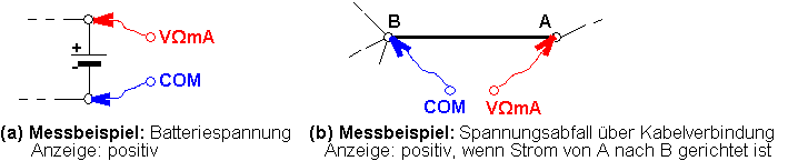
0.4
Measurement of voltage, current and resistance with a digital multimeter
Usual
designation of the input sockets
COM:
Connection of the minus measuring cable
VΩmA:
Connection of the (plus) measuring cable for voltage [V], resistance [Ω] or current
measurement [mA]. The additional label "FUSED 200mA MAX" means
that the current measuring path is internally fused with 200 mA to
protect the device.
UNFUSED 20Amax:
Connection of the measuring cable for current measurement in the range from 200
mA to 20 A. The device is not protected in this area, exceeding the maximum
current (here eg 20 A) will destroy the device.
Safety rule: Always start measurement with the
largest measuring range!
Voltage
measurement
The voltage is
measured in the unchanged system between two selected contact points. The point
to which the COM cable leads is used as the reference point for the displayed
polarity of the voltage value. COM is preferred connection for ground. If you
swap the measuring cables, the same numerical value is displayed for the
voltage, only with the opposite sign.
Common errors:
a) If the fused current
input socket was accidentally used for an intended voltage measurement, the
internal fuse of the device usually blows
, which often goes unnoticed for a long time!
b) If AC voltage is
incorrectly measured in the DC voltage range, the display is always close to
zero.
Current
measurement
To measure the
current , the line in which the current to be measured flows must be
disconnected. This is expediently done at a connection point.
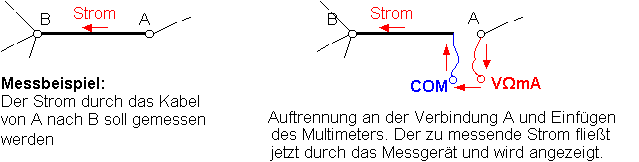
If the multimeter
fuse has blown , zero is always displayed for the current!
Resistance
measurement
For resistance
measurement , the element must be separated from the system by at least one
connection , otherwise incorrect measurements will occur.

Special
measurement problems
Measurement
of very high resistances (> 10 kΩ): Do not bridge the
measurement connections with your fingers during the measurement, because the
parallel body resistance falsifies the result.
Measurement
of very small resistances (<10 Ω): Before the
measurement, bring the ends of the measuring cables together and read the value
(lies in the range of 0 .0.5 Ω). The
correction value determined in this way must then be subtracted from each
measured value. If the measuring cables are exchanged, the correction value
must be determined again.
Measurement
of the smallest resistances (<10 mΩ): A known
current is sent through the resistor - if possible - and the voltage drop is
measured directly (!) At the resistor. The value is calculated as R = U / I.
For illustration: measuring current 1A, measured 1 mV results in R = 1 mV / 1 A
= 1 mΩ.
Fidgeting display or implausible
values with digital multimeters
Digital measuring
devices are usually more nimble than analog pointer instruments. This can lead
to short interference pulses (e.g. from the ignition) being detected and causing the display values to jitter. For
this reason, the measuring lines should generally be routed as far away as
possible from cables and ignition equipment. With DC voltage measurements, a
ballast as shown below can help in stubborn cases. Interfering frequencies>
30 Hz are thus suppressed. If this is not enough, the capacitor can be
increased (e.g. 10 times the value). The larger the capacitor, the more
effective the suppression of voltage fluctuations, but the slower the response
of the display.
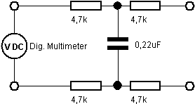
DC voltage filter as ballast
Such malfunctions do
not normally occur in vehicles with an intact electrical system. It is
therefore important not to be satisfied with eliminating the symptoms, but to
look for the causes of the interfering impulses. The following are to be
examined: spark plug connector (internal flashovers), ignition capacitor (ineffective),
collector (grooves, nicks, scaling) or slip rings (breakouts), regulator
contacts (burn-off), loose contacts / broken cables, fuse contacts (corrosion).
A DC
generator and 6 V electrical system
A.1
Field-regulated DC alternator for 6 V vehicle electrical system
A.1.1
Checking the winding resistances
Before the LiMa is tested with the motor
running, the winding and insulation resistances should be checked (for
setpoints, see Table A.1-3). Since the measurement of very small or very large
resistance values harbors particular risk of error, the
instructions in Section V.3 must be observed.
If slightly higher values occur
with certain rotor positions, sanding the copper lamellas with 500 grit
sandpaper often helps.
If the rotor continues to turn, it is possible
that the multimeter display goes "crazy". This has to do with the
fact that the residual magnetism induced when the rotor moves a voltage that
confuses the resistance measurement. The reading is only to be taken when the rotor
is at a standstill!
The actual insulation resistances are mostly
over 20 MΩ.
Fig. A.1-1: 6 V / 10 A / 60 W DC generator of
an ES150, exciter series resistor R has been removed (yellow symbol R)
|
Test
object |
Measurement
conditions |
Resistance
measurement between |
LiMa 6 V / 60 W. |
LiMa *) 6 V / 30 W. |
|
Rotor- winding |
Loosen the
copper wire of the minus carbon Loosen the
D + cable Loosen the
D + side connection from R. Slowly turn
the rotor 360 ° during the measurement so that all segments of the collector
are checked. |
D + and
loosened copper braid of the minus coal |
(0.2 ± 0.2) Ω |
(0.8 ± 0.2) Ω |
|
Rotor- isolation |
- ditto - |
D + and
ground |
> 1 MΩ |
> 1 MΩ |
|
Field- winding |
DF + sided Loosen
connection from R. Loosen the
DF cable Loosen the
DF winding end from the ground |
DF + and
DF- |
(1.7 ± 0.3) Ω |
(2.6 ± 0.3) Ω |
|
Field- isolation
|
- ditto - |
DF + and
ground |
> 1 MΩ |
> 1 MΩ |
|
R. |
Both
connections solve from
R. |
|
(4.5 ± 0.5) Ω |
unavailable |
|
R insulation |
- ditto - |
any Connector
and metal body |
> 1 MΩ |
unavailable |
Table A.1-3: Setpoints for winding and
insulation resistances
*)
LiMa 6 V / 30 W for RT125 / 0-2
Definition
of "plus or minus regulation" for vehicles with a negative pole on
the chassis according to [5]
In the plus-regulated
LiMa , the plus- side field winding connection (DF +) is led to the
controller connection (DF).
The minus-side field winding connection (DF-)
is connected to ground (D-) (see Figure A.1-2a). If an excitation field series
resistor R is available, it is connected between D + and DF.
With the minus-regulated
LiMa , the minus- side field winding connection (DF-) is led to the
controller connection (DF).
The positive-side field winding connection (DF
+) is connected to D + (see Figure A.1-2b). If an excitation field series
resistor R is available, it is connected between DF and D-.
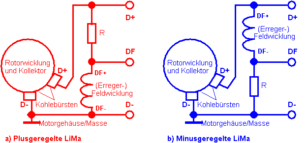
A.1-2: Alternator, electrical block
diagram
DF- negative
end of the field winding,
DF + positive end of excitation field winding
DF controller
connection for field winding
R series resistor for field winding
(not applicable when using electronic
controllers)
D + positive
collector carbon brush (short: plus
carbon)
D- negative
collector carbon brush (short: minus carbon) = ground
The excitation field series resistor R is often designed as an external resistor
(see Fig. A.3-1), but it can also be used in the excitation field winding
itself (e.g. RT125 / 3 series partially) or in the electro-mechanical
controller (e.g. IFA RT 125 ) be integrated.
Plus and minus rules are of equal importance , they have neither advantages nor
disadvantages in relation to the other type of circuit. There are also no
differences in terms of the magnetic or electrical polarization of the LiMa.
If the winding ends of the excitation field
winding are accessible, a minus-regulated LiMa is created by reconnecting the
field winding connections to a plus-regulated one and vice versa. If it is a
field winding in which the excitation field series resistor is integrated
(feature: 3 connections emerge from the stator), it is no longer effective
after the conversion, so that an external resistor must be provided.
If the control type is specified, this has an
impact on the design of the controller. The plus regulator must
"send" a positive current into the DF + connection so that the
generator voltage increases, the minus regulator must "pull out" a
positive current from D- to achieve the same effect. As a visual comparison,
imagine a tube with a suction pump connected to the left in the first attempt
and a pressure pump to the right in the second attempt. The liquid flows
through the tube in the same direction in both cases, but the pumps are of
different construction.
All MZ two-stroke engines are plus-regulated,
the exceptions are the BK350 and the last series ETZs (around 1990) with a
regulator circuit.
With the RT125 / 3 there are irritations
as to whether the plus or minus control was originally intended or whether a
changeover occurred during series production. Separate controller types would
then be required for plus and minus regulations. So far, only plus-regulated
systems could be found in RT125 / 3 vehicles that had been checked in practice
and were apparently in their original condition.
It can therefore be assumed with a very high
degree of probability that the RT125 / 3 is generally plus-regulated .
The cause of this confusion is possibly an
error in the circuit diagram of the RT125 / 3, which is in the original
operating instructions and which is also found in other publications. The error
can even be found in the diagram on the inside of the bobbin case cover. The
exciter field series resistor is incorrectly drawn in parallel to the field
winding, which makes no electrical sense.
A.1.2
Alternators - function test
If the resistance
measurements according to A.1.1 do not show any irregularities, the LiMa can be
tested with the engine running. All cables (D +, DF +) leading to the
controller must be disconnected and secured beforehand. In this test, a fault
in the rotor (e.g. winding short) can be detected if the voltage at D + does
not reach the orientation value mentioned above.
Fig.
A.1-4: LiMa
test circuit with external excitation
After connecting the
battery, the 6 V lamp lights up and a current of around 1.8 A is impressed into
the field winding. The engine is now started normally (on battery ignition) and
the voltmeter is observed. If the speed is higher than idle, the generated DC
voltage must quickly rise to 10 ... 12 V with an intact LiMa and the 12 V lamp
connected as a load lights up. If the 18 W incandescent lamp is removed, the 60
W lamp goes out regardless of the speed.
Caution: Do not
increase the equivalent speed beyond 12 V, the light bulb can burn out!
To be on the safe
side, if all previous measurements and tests were successful, the
self-excitation can still be checked. To do this, all lamps are disconnected
when the motor is at a standstill and a wire bridge is inserted between DF +
and D +. The engine will start again. A voltage of 12 ... 15 V must be
generated at a slightly increased speed. Incidentally, this situation
corresponds to the push-on position of the ignition light switch. However,
since the controller is not effective in this test, it should last a maximum of
10 s in order not to overload the field winding.
Self-excitation
requires a sufficiently large residual magnetism in the iron core of the
windings. If this has been lost or there is a magnetic reversal of polarity
(e.g. if the LiMa has been stored in the earth's magnetic field for a long
time), it can be assumed that sufficient residual magnetism will remain after
the function test described above has been carried out.
The magnetization or
magnetic correct polarity can, however, also be brought about a little more
aggressively by bringing the positive terminal of the battery (unsecured!) Into
contact with D + for a moment (0.1 s).
A.2
Electromechanical controller (E / M, 6V)
A.2.1
Mechanical adjustment
The structure of the electromechanical voltage
regulator was kept almost unchanged from the first RT in 1950 to the 12 V
systems of the ETZ series of the 1990s. Deviations can be found in the details,
e.g. in the mechanical design of the bending elements.
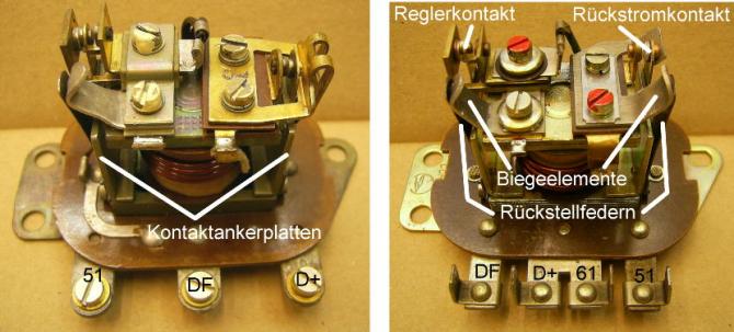
Figure A.2-1: Designation of the contacts and setting elements on the
electromechanical
Controller, older on the left, newer on the
right
In the literature [1] and [2] you can find
different adjustment measures. Based on this information, sensible orientation
values have been set in Figure A.2-2 (blue entries).
Control of the mobility of the
contact anchor plates
First it is checked whether the contact tongues
can be pressed easily up to the core without the angled lower ends of the
contact anchor plates sitting on the core foot. In the relaxed state, a
dimension of 0.5 mm is given in [1]. If nothing sticks, nothing should be
changed in the current distance, even if the value is not exactly 0.5 mm!
Setting the controller contact (left
side)
The setting of the magnetic gap (1 mm) and the
controller contact spacing (0.4 mm) takes place in one step, as both fixed
contacts can be moved after loosening the upper cylinder head screws. The
magnet gap (1 mm) is set by moving the left fixed contact and the contact
distance (0.4 mm) by moving the right fixed contact.
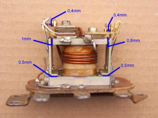
Fig. A.2-2:
Orientation values for the distances to be set
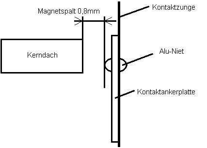
Image A.2-3: Determination of the gap width with existing aluminum rivets
in the contact anchor plate
This attitude requires skill and patience. And
it has to be right in the end when the cylinder head screws are tightened
again! If you hit the target values within ± 0.1 mm, you can be satisfied.
Setting the reverse current contact
(right side)
Magnet gap (0.8 mm) and contact distance (0.4
mm) are also set simultaneously after loosening the corresponding cylinder head
screws. The contact distance (0.4 mm) can be set with the left fixed contact. Here,
too, a setting accuracy of ± 0.1 mm should be aimed for.
Note
As soon as mechanical changes are made to the
controller, changes to the electrical setting values are to be
expected, so that subsequent electrical adjustment is absolutely necessary!
A.2.2
Electrical adjustment
The connection
sequence applies to older controllers (see Fig. A.2-1) with screw connections:
51 DF D
+ / 61
The plug contact
version has the following sequence:
DF D +
61 51
where D + and 61
have separate contact lugs, but are connected to one another. The ground
contact is on the base plate of both controller versions.
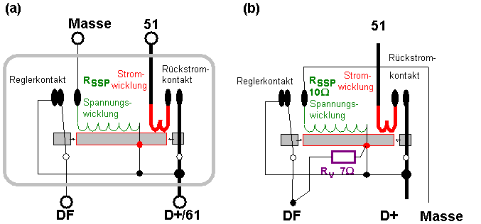
Fig.
A.2-4:
(a)
Functional diagram of the electromechanical regulator for the 6V / 60W
generator.
(b)
Regulator of the 6 V / 30 W LiMa for the RT125 / 0-2 with integrated field
winding series resistor
Preliminary
test of the controller with the help of resistance measurements
(unused connections
remain open)
The resistance of
the voltage coil R SSP was determined from our own
measurements on several copies of 6 V / 60 W regulators with different
production dates. The last measured coil resistance with 10 Ω was
marked 3/76 and the first with 20 Ω was marked 4.80. The conversion must therefore
have taken place between 1977 ... 1980.
The reason for this
could be a desired reduction in the wire cross-section of the voltage coil. In
addition to saving copper, this also reduced the controller's power consumption
from around 5 W by 50% to 2.5 W.
Before the
measurement, the contacts must be cleaned with a strip of hard, transparent
drawing paper (parchment), otherwise the small contact resistances of 0.2 Ω and less are hardly
achievable!
|
element |
Resistance Measurement between the connections |
condition
|
Value
for Regulator of 6V / 60W- LiMa |
Value for Regulator of 6V / 30W LiMa RT125 / 0 ... 2 |
|
Voltage coil |
D + / 61 and mass |
|
R SSP |
R SSP (10 ± 0.5) Ω |
|
Controller contact |
D + / 61 and DF |
Rest position Middle position pressed on |
0 ... 0.2 Ω infinite R SSP |
0 ... 0.2 Ω R V (7 ± 0.5) Ω R SSP
// R V (4 ± 0.5) Ω |
|
Controller contact |
Dimensions and DF |
Rest position Middle position pressed on |
R SSP infinite 0 ... 0.2 Ω |
R SSP (10 ± 0.5) Ω R SSP + R V (17 ± 0.5) Ω 0 ... 0.2 Ω |
|
Reverse current contact |
D + and 51 |
Rest position pressed on |
infinite 0 ... 0.2 Ω |
infinite 0 ... 0.2 Ω |
Table
A.2-5:
Setpoints for resistance measurements on the controller.
R SSP :
voltage coil resistance up to the end of the 1970s: (10 ± 0.5) Ω from the beginning of the 1980s: (21.5 ± 1) Ω,
R V :
field winding series resistor
Notes on
measuring the RT125 / 0-2 controller relay when it is removed
On the rear side
(inside the coil box) the lead out connection corresponds to terminal 51. On
the front side of the regulator relay (facing outwards in the coil box) there
are 3 wire connections. DF is the first connection that leads to the middle
contact spring of the controller contact. DF must be connected to the second
connection coming out of the winding! Ground comes as a third connection from
the inner fixed regulator contact. D + is to be connected to the bottom of the
metallic core of the coil former. If the controller is measured in the coil box
on the vehicle, all cables leading to the outside must be loosened from the
screw terminals.
Electrical adjustment of the controller
Confusing
facts from the literature [2]
The information on
the electrical adjustment of the 6 V regulator in the literature [2] (see Table
A.2-6) is hardly practicable; the problem is explained below. The recommended
procedure is shown on the next page.
The information from
[2] is given in Table A.2-6. Compliance with the specified speeds can at best
be estimated for the TS and older models that do not have a tachometer.
|
Pick-up voltage reverse current contact |
6.5V ... 6.9V |
|
Drop-out voltage reverse current contact |
5.4V ... 6.2V |
|
on-board voltage to be set for N = 1800 ... 2200 min-1 and 10 A load |
6.2V ... 6.8V |
A. |
|
on-board voltage to be set for N = 4000 min-1 for continuous daylight operation
|
6.8 V ... 7.2 V |
B. |
Load
case A: low beam (40 W) + rear light (5
W) + stop light (18 W) = 63 W,
gives
a total of 10 A at 6.3 V and disconnected battery
Load
case B: Not further defined
Table
A.2-6: Voltage values for electrical adjustment taken
from the
Literature [2]
The usual load in
solo daylight mode is 40 W (low beam) + 5 W (rear light), which is around 8 A.
In addition, there is an average of 2 A for the ignition coil, which adds up to
10 A. Turn signals and stop light are consumers that usually only work for a
short time. When fully charged, the intact battery takes up almost no more
charging current. It can be seen from this that the two load cases A and B
hardly differ at all.
For the daylight
operation prescribed today, 6.8 ... 7.2 V should be set according to the table.
With a permitted 7.2 V, however, at 25 ° C one would already be at the gassing
limit of the lead-acid battery (see Section V.2). If you consider that the
setting accuracy of the mechanical regulator is often worse than 0.1 V and that
changes also occur due to wear and tear of the contacts during operation, the
battery could endure if you just hit the upper limit of the permitted range
would meet.
In addition, the
table allows the reverse current contact to be adjusted to 6.9 V in extreme
cases, but the on-board voltage comes to a maximum of 6.8 V. According to the
table, this would be permitted, but fatal, since the LiMa would then never be
connected to the on-board network or the battery.
For all of the
reasons mentioned above, sensible
setting values that
have proven themselves in practice are therefore suggested in the following
work steps .
Adjustment
and preparation procedure
The sequence of the
work steps must be strictly adhered to.
1) Adjustment of the pull-in voltage
of the reverse current contact
2) Check
the dropout voltage of the reverse current contact
3)
Voltage adjustment of the regulator contact
4)
Checking the charging voltage in the vehicle under normal operating conditions
Before setting,
clean the contacts with a strip of hard, transparent drawing paper or
parchment! In stubborn cases, sandpaper with a grain size of 500 or finer
should be used.
1) Inrush voltage of the
reverse current contact
The reverse current
contact must close when the generator voltage exceeds the typical open circuit
voltage of the battery (6.3 V). This results in a meaningful target area for
the
Pull-in
voltage of the reverse current contact: (6.4 V ± 0.1) V .
The voltage of the
controllable voltage source is slowly and continuously increased starting from
zero (measuring circuit see Fig. A.2-7) until the contact picks up (= lamp
lights up). If the tension is too low , the
associated bending element must be bent outwards in
order to increase the restoring force of the contact restoring spring or vice
versa.
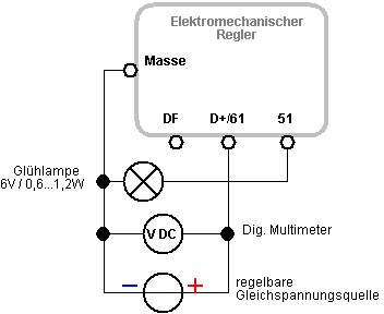
Fig.
A.2-7: Circuit
for voltage adjustment
of the reverse
current contact
Since the bending elements made of aluminum or
brass become brittle after a few rough bends and can break off, you should work
very carefully and avoid unnecessary bends.
If several switching attempts are carried out
under the same conditions, the reproducibility of the switching point will
usually be poor. Experience has shown that fluctuations of ± 0.1 ... ± 0.2 V are typical. The
reasons for this are: wear of the contacts, variable residual magnetism in the
core, changes in properties due to the relay heating up during the adjustment
procedure.
2)
Check the dropout voltage of the reverse current contact
In order to control
the drop-out voltage, the reverse current contact is first closed by
increasing the voltage (= lamp lights up), whereby the voltage must be
increased further until the contact anchor plate or the aluminum rivets
are completely in contact with the core. Only now is the voltage slowly and
continuously reduced until the reverse current contact drops out (= lamp goes
out). According to the information
from [2] (see Tab.
A.2-6) the permissible range for the drop-out voltage is 5.4 ... 6.2 V. The
voltage should not be lower than 5.4 V, as the battery is then with Idle speed
increasingly against the LiMa begins to work. However, nothing can be adjusted
if the dropout voltage should be lower than 5.4 V.
3)
Voltage adjustment of the regulator contact
The measuring
circuit according to Figure A.2-8 only differs from the previous one in that the
test lamp is now connected to terminal DF. The voltage of the controllable DC
voltage source is increased slowly and continuously from zero. We observe that
the return current contact is first tightened (click), and when it is increased
further, the armature plate of the return current contact hits the core
(click). Both processes (click - click) can also take place almost at the same
time.
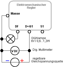
Fig. A.2-8:
Circuit for voltage adjustment of the regulator contact
As the voltage
increases, the brightness of the incandescent lamp increases. If the voltage is
so high that the regulator contact anchor plate is attracted, the regulator
contact opens and the bulb goes out.
Then we increase the
voltage by a further 0.3 ... 0.5 V and observe how the regulator contact moves
evenly beyond the central position in the direction of the inner fixed contact.
However, if the regulator contact armature is suddenly pulled to the core
shortly after it has been lifted off, the two fixed contacts must be pushed
outwards by a few tenths of a millimeter in parallel. To do this, loosen the
screws originally secured with paint. After this correction, the anchor plate
distance to the core is slightly larger than specified in the mechanical
presetting. Then check that the contact moves evenly beyond the central
position.
Now the switching
point of the controller contact is delicately limited by increasing or
decreasing the voltage several times (light bulb alternately "on"
<-> "off"), then measured and recorded. In an optimum
charging voltage of 6,9V plus a derivative of 0.2V (voltage drops via
cable, securing, etc.) as a set value 7.1
V sought.
If the voltage is too low , the associated bending element
of the controller contact (see Figure A.2-1) must be
bent outwards in order to increase the
restoring force of the contact restoring spring. If the
tension is too high, bend the bending element inwards
.
You should definitely get an impression of the
extraordinary sensitivity of the setting before
re-bending by tucking a piece of paper under the return spring and
observing the change in the switching voltage. Experience has shown that this
manipulation leads to value changes of up to +0.5 V depending on the thickness
of the paper strip.
Since the bending elements are made of aluminum
and become brittle and break off after repeated bending, you should absolutely
avoid unnecessary bending.
The setting of the
RT125 / 0-2 controller for the 6 V / 30 W LiMa is possible with the specified
circuit. Because of the integrated series resistor, the light bulb does not go
out at the switching point, but only becomes slightly darker. The difference in
brightness at the switching point is small and therefore more difficult to
perceive.
4)
Checking the charging voltage in the vehicle under normal operating conditions
Before checking the vehicle, make sure that the
cabling is OK and the contacts (especially on the fuses) are in good condition
in order to keep voltage drops to a minimum.
The controller is installed in the vehicle and
the engine is started. "Usual operating conditions" mean here:
Slightly increased speed compared to idling (corresponding to about 2000 ... 3000min
-1 ) and low beam on. Now the voltage is measured directly at the
battery terminals. Under normal ambient temperature conditions (15 ° C ... 25 °
C) this is 6.9 V.the desired setting value. Since a few amps of load
current (headlights, taillights, ignition, battery charge) flow through the
controller's current coil, the control voltage systematically decreases by 0.3
... 0.5 V compared to the original setting after step 3. The correction
increases higher tension values can easily be achieved by placing
strips of paper underneath the contact spring, which prevents the bending
elements from bending.
Electromechanical controllers change their
properties over longer periods of operation. It is therefore advisable to check
the charging voltage on the battery every year as described above and to
adjust it if necessary.
Electromechanical regulators do not regulate
load fluctuations ideally, so that, for example, when the low beam is switched
off, the charging voltage jumps up by up to half a volt.
Anyone who has set the regulator according to
the above regulation, but afterwards thinks that they have to do something good
for the battery by driving without the low beam, will achieve exactly the
opposite. The higher charging voltage will very likely exceed the gassing limit
of the battery and reduce its service life or even lead to destruction!
A.3
Electronic controller (6 V)
A.3.1
Removal of the regulator resistor
If the electromechanical controller is replaced
by an electronic one, it is necessary to remove the field winding series
resistor. Figure A.1-1 shows the LiMa already with the regulator resistor
removed.
It is also possible to leave the series
resistor in the LiMa and simply put it out of operation. This has the advantage
that when upgrading to an electromechanical controller, all parts are available
and you only have to reconnect. The two connecting wires of the series resistor
are screwed together under the fastening screw of the winding body foot (earth)
(see Figure A.3-1).
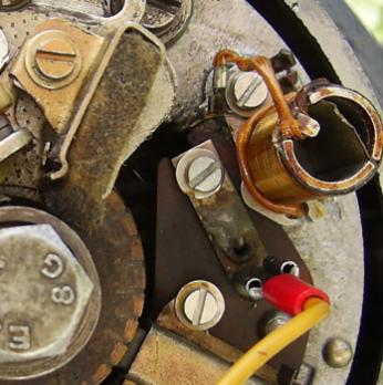
Fig. A.3-1:
Deactivated field winding series resistor
(both connections clamped under fastening)
If the controller in the coil box of the
RT125 / 0-2 is replaced by an electronic version, no measures are
required, as the field winding series resistor is integrated in the controller
relay and is therefore removed when it is removed. With the RT125 / 3 ,
the series resistor is located in the LiMa as usual and must be removed or
rendered ineffective.
A.3.2
Electronic controller - function test
Most electronic controllers (analog principle)
can be tested for function with the
same test circuit as was used for the electromechanical in the removed (or
"disconnected") state.
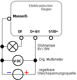
Fig. A.3-2:
Circuit for the function test
of the electronic controller
When the voltage at D + / 61 is increased, the
brightness of the lamp initially increases to the same extent. When the cut-off
voltage is reached and exceeded, the incandescent lamp goes out. In principle,
this can be done "gently", that is in the range of a few tens of mV.
The switching point is therefore determined at
medium brightness of the lamp. Since most electronic regulators use a
semiconductor diode as a non-return valve, the value of the cut-off voltage at
the switching point must be equal to the amount of the diode forward voltage
(Si-pn diodes: 0.8 V ... 1.0 V, Schottky diodes 0.4 V ... 0.5 V) higher than
6.9 V.
Cut-off voltages of 7.3 V ... 8.0 V
are therefore classified as unsuspicious.
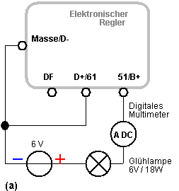
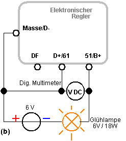
Fig. A.3-3:
Circuit for testing the non-return valve
In case (a), the incandescent lamp must remain
dark. The reverse current displayed by the multimeter should be well
below 1 mA (typically µA range).
If one takes 1mA as the value for the diode
reverse current in the worst case , then calculated over a month this would
cause a creeping discharge of the battery of 30 x 24 hx 1 mA = 0.72 Ah and would
just be acceptable.
In case (b) the incandescent lamp lights up and
approx. 2 A flow. In this case, the multimeter shows the diode forward
voltage of the reverse current diode , which is approx. 0.8 ... 1.0
V (for Schottky diodes 0.4 .. .0.5 V).
Due to the differently designed products, when
using an electronic controller, it is very important to check the voltage on
the battery under real load and operating conditions in the vehicle after the
successful function test.
Usually nothing can be set on the electronic
controller, so that you can only find out whether the battery charging voltage
is acceptable or not (see section V.2.3 "Checking the operating conditions
in the vehicle electrical system").
In a pinch, however, which can be Controller
voltage by inserting a diode at 51 / B + to a diode forward voltage lower
. When attaching the diode, however, its
power consumption of up to 10 W must be taken into account.
A.4 Contact ignition system (6 V)
A.4.1 Overview
This section is
about checking all components of the ignition circuit for proper function. Instructions
for setting the breaker ignition can be found in Chapter V.7. The ignition
system includes the breaker contact actuated by the crankshaft cam, the
ignition capacitor, ignition coil, ignition cable, spark plug connector and
spark plug. Experience has shown that faults in the ignition system are the
most common cause of engine failure. If only one of the heavily used components
fails, the entire system fails.
A.4.2
Contact, ignition capacitor
In order to include the lead to the ignition
coil when checking the breaker contact, the cable at terminal 1 is disconnected
from the ignition coil for the duration of the measurement and the resistance
to ground is measured at the end of the cable.
(a) Contact closed: <0.1 Ω * *) Definitely measuring tips
(b) Contact open: > 1 M Ω * note in chapter V.3
It usually takes a while until a correct
resistance value is displayed for measurement (b), as the ignition capacitor
lying parallel to the contact has to be reloaded by the measuring device.
If the values do not come true,
the following causes (among others!) May be present:
(a) resistance greater than 0 , 1 Ω : corroded breaker contacts, dirty or worn out,
cable or clamping points (see Section V.1..) is defective or unreliable
(b) Resistance much less than 1 M Ω : Cable
insulation defective, capacitor has plate connection
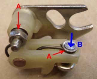
Figure A.4-1: Problem areas on the contact spring
(A) and contact riveting (B)
A more precise
assessment of the closed interrupter contact
is possible if the voltage drop between the connection lug of the capacitor and
ground is measured. When the ignition is switched on, a contact current of
approx. 4 A flows in 6 V systems, and 2.7 A in 12 V systems. The voltage drop
above the original
MZ contacts is
typically around 90 mV or 60 mV. If it is significantly larger, the 3 measures
outlined below can possibly bring about an improvement:
1) Smooth out eroded
contacts with a contact file.
The burnished wire
spring and the two contacts A (see Fig. A.4-1) cause a considerable proportion.
2) Carefully file the
wire spring eyelet under the M3 nut until it is bright or add an M3 tooth lock
washer.
3) Rivet the rivets
on the upper contact. For this purpose, the lower contact plate is placed on a
metal plate and a punch is placed on the flat head B. With a few blows, the
upper contact is slightly mushroomed and the contact resistance is reduced.
The result can be
checked by measuring the voltage drop again. If no improvements are possible,
the contact should be exchanged.
The capacitor can stand
on its own when removed
·
Isolation
(resistance> 1 M Ω ) and
·
Capacity (0.22 µF + 20%
/ -10%) can be checked.
If the capacitor values are OK at
room temperature, this does not necessarily mean that correct functioning is
guaranteed even if the temperature in the motor housing is increased. Failures
that only occur at engine operating temperature and "heal" again when
cold are possible.
In the case of defective ignition capacitors
(before 1990), for example, when heated to 100 ° C, a sharp drop in insulation resistance
(<< 1 M Ω) with a
simultaneous increase in capacitance (up to 5 times the nominal value), which
led to misfires. To heat up the capacitor for a heat measurement, immerse it
about 1 cm deep for about 5 minutes in boiling water and measure resistance ( > 1 M Ω) and capacitance (0.22 µF + 30% / -20%) immediately
after Remove. It is important to ensure that the potting gap on the housing and
on the contact does not come into contact with water, as it easily penetrates
as it cools down.
A.4.3
Ignition coil
The function of the
ignition coil is a transformer with a primary (index 1) and secondary coil
(index 2). Every technical coil is determined by its inductance L (in H) and
its winding resistance (in Ω ). The
parameters of the equivalent circuit of the 6V ignition coil were determined
and averaged experimentally on several specimens.
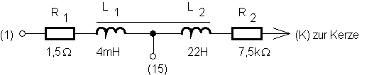
A.4-2:
Equivalent circuit
of a 6V ignition coil
Although there is a
series connection of resistance and inductance between terminals (1) and (15)
as well as between (15) and (K), the digital multimeter only records the
resistance because it is measured with direct current. The multimeter does not
"see" the inductance when measuring resistance, just like when
measuring winding resistances in the LiMa.
The nominal values
for winding and insulation resistances are listed in Table A.4-3.
In any case, short circuits and ground circuits as well as winding breaks can
be found.
|
element |
Measurement between |
resistance |
Approximate values
for RT125 / 0-3 |
|
|
|
|
|
|
Ohmic resistance of the primary coil |
(1) and (15) |
(1.5 ± 0.2) Ω |
1.3 Ω |
|
Ohmic resistance the secondary coil |
(15) and K |
(7.5 ± 1) kΩ |
3.3 kΩ |
|
Insulation resistance |
(1) and housing such as (15) and housing such as (K) and housing |
> 1 M Ω each |
|
Table
A.4-3: Winding and insulation resistances of the 6V ignition
coil
Poor contact between
the ends of the windings (1) and (15) is a fault that sometimes only
appears when heated up due to sporadic misfiring. In order to improve the
contact, the contact caps of the ignition coil are unscrewed and their inner
surfaces are made bare with a fiberglass brush. The winding ends are very
carefully scratched (if the wire breaks!) Until the copper shine can be seen
(Fig. A.4-4). To counteract further corrosion, a little Vaseline grease can be
put under the caps before putting them on.
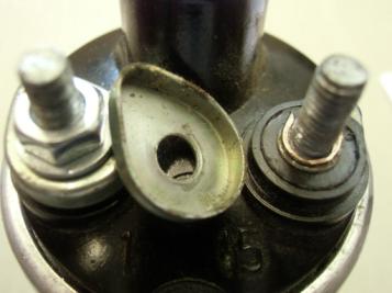
Figure
A.4-4:
Dismantled contact cap on the
ignition coil
If the resistance
values are within the tolerance, this does not necessarily mean
that the ignition coil is OK. Internal voltage flashovers can already occur in
the cold state if the properties of the insulation material have changed.
Similar to the
ignition capacitor, thermal problems often lurk in the ignition coil, which
remain hidden when measuring on the workbench when it is cold.
The reasons for this
are thermal changes in the winding and insulation properties as well as
chemical effects after penetration of moisture. In the latter case,
electrochemical elements can even form (copper winding - water - aluminum
housing). On a defective specimen, after heating, a direct voltage of up to
1000mV was found between the open terminals (1) / (15) and the aluminum
housing. If the coils are faultless, the values are well below
10mV.
Good statements can
be made with the test setup described below
Win picture A.4-4. The
circuit corresponds to a minimum ignition circuit set up outside the vehicle
(see Figure A.4-6), but instead of the spark plug, an adjustable spark gap
(ignition voltage tester) is used. The voltage source (lead battery) is
selected according to the nominal voltage of the ignition coil to be tested. Since
higher ignition voltages are generated during the test than is the case in
normal operation, higher primary voltages (up to 500V) can also occur at
terminal (1). Instead of the usual ignition capacitor, a more voltage-resistant
(0.22µF / 2000V) must be used.
In order to achieve
reproducible, bounce-free switching processes, the use of a mercury switch (Hg
switch, Hg tilt switch) is required. All components of the test site are
currently (2014) still available in relevant motorcycle accessories and
electronics stores. However, it is to be expected that mercury switches will
disappear from the range in the future, as has already happened with mercury thermometers. Experienced
electronics engineers can, however, also replace the Hg switch with a
voltage-proof transistor ignition.
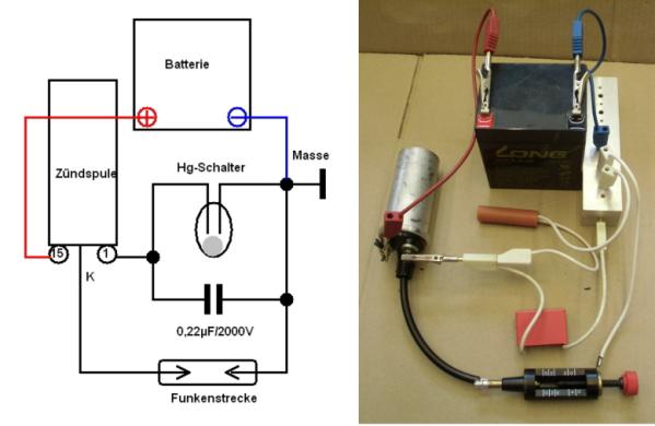
Fig. A.4-5:
Circuit and practical structure for testing ignition coils
Safety note: In particular, people with impaired health are
strictly discouraged from operating the test station. Accidental sparkover on
any part of the body can be life-threatening.
The electrode spacing of the spark gap is
always changed when the battery is disconnected. 6 V ignition coils have a
maximum spark length of 8 ... 10mm, 12 V ignition coils 10 ... 15mm. High humidity has a strong influence on the spark length that can
be achieved. In dry air, a breakdown field strength of 3kV / mm is expected. 10mm
spark length means 30kV voltage!
The ignition coil is heated up by keeping the
Hg switch permanently closed. The heating process is carefully monitored. Excessive
heating will destroy the ignition coil. After 3 to 5 minutes, a temperature has
usually already been reached that just barely allows the housing to be touched.
The spark test is now repeated with the ignition coil warmed up. Based on
previous experience, a reduction in the maximum spark length of 20% can be
regarded as normal. If the reduction is greater, it must be assumed that the
heated ignition coil in the vehicle can cause ignition problems.
A.4.4
Ignition cable, spark plug cap and spark plug
Ignition cable
In the case of the ignition cable, lengthy
measurements will be dispensed with and if mechanical wear of the copper core
at its ends or visible corrosion can be seen, it will be replaced. If it should
nevertheless be checked: The copper core has a very small resistance, which,
within the scope of our measurement accuracy, would have to be specified as
(0.0 + 0.1) Ω . However, there are also cores
made of resistance material, whereby the cable is then supposed to take over
the function of the interference suppression resistor. The cable resistances in
conventional lengths are then in the order in which the values for suppression
resistors are, therefore, 1 k Ω to several 10 k Ω. These cables work well with our MZs if the
ignition system has no weaknesses elsewhere. If you are unsure, you can make no
mistake about replacing such a cable with one with a normal copper core.
Spark plug connector
There is usually an interference suppression
resistor (1 k Ω ... 10 k Ω ) in the plug connector . The value is
usually noted as an indication on the connector, although there are also
connectors without resistance, i.e. with zero Ω .
When measuring the continuity from the
cable-side connector input to the plug-side contact, this value must be
verifiable to ± 20%. Infinite resistance means that there is an interruption,
the plug must be replaced, even if it strangely still works, because the
interruption may be overcome by a flashover inside.
If the connector is sheathed in metal, the insulation
resistance to the sheet metal sheath must be well above 1 M Ω .
Persistent moisture at the connection points between ignition cable
- ignition coil and ignition cable - spark plug connector often leads to
ignition failure. As is well known, this happens suddenly in heavy rain or
creeping in with morning pew. Tightly fitting and non-porous sleeve sleeves
protect against this, but also keep moisture that has penetrated in for longer.
The sheet metal jacket of the candle holder is also a moisture collector in
this regard. If the "originality" does not suffer and nobody
complains about radio interference, you should remove the sheet metal covering
of the plug connector with suitable pliers.
spark plug
The candle is almost impossible to get at by
measuring it. Only the traditional method of subjectively assessing the spark
at the electrodes according to its strength helps here. It has to be strong and
bluish-white, accompanied by a clearly audible crack. One speaks of the crisp
spark ...
However, it must be taken into account that
there are high temperatures and high pressure in the cylinder, which can mean
that the candle that has passed the roadside visual test nevertheless reacts
with "spark silence" in the cylinder. Only a (really !!!) fresh
candle will help. And if it should then work satisfactorily, the most important
action is still to come, namely to actually throw away the defective candle!
Honestly, I didn't always do it consistently, and what was the result? That
at some point - all previous history is forgotten - after years you will screw
in the same cucumber again and bring yourself to the brink of despair through
your own fault.
The value of the interference
suppression resistor (s) in the ignition circuit
can vary within wide limits without adversely
affecting the proper function, whereby an overall intact ignition system is
assumed.
If the candle is weakening and moisture
has crept into the ignition cable and the battery is at the end of it,
increasing the interference suppression resistor from 0 to 100 kΩ may tip the scales, which in no way means that
the above thesis is wrong.
It even sparks with a blade of grass in the
"high resistance area" instead of the ignition cable and also
with a suppressed candle (NGK BR ...) and a suppression resistor in the
plug! The participants at the forum meeting in Sosa 2008 were able to see this
for themselves with their own eyes and ears.
Anyone who has the experience that it ignites
"noticeably" better without resistance should not be talked out of
this for the Buddha's or whose will. It is important that you have personally
gained a positive experience and are happy with it from now on. And zero point
zero ohms are not wrong either!
Minimum ignition circuit
If there is no ignition spark or if the
ignition is unreliable, it is worth setting up a "minimum ignition
circuit" as shown in Figure A.4-6. Only the absolutely necessary
components are used in order to exclude possible errors in the wiring of the
machine as well as short circuits, line breaks, fuse problems and the ignition light switch.
Figure A.4-6:
Structure of a minimum ignition circuit
As long as this structure does not work, there
is little point in looking for the fault elsewhere. If it works, however,
please note that the engine can only be stopped by disconnecting the battery!
The ignition circuit - hardness test
The best way to check whether an ignition system
is "overall intact" is with a spark gap. The breakdown limit for dry
air is around 3 kV per millimeter. A U-shaped plastic plate and a plastic
clothes peg are used to fix the ignition cable that has been detached from the
spark plug connector. The copper core must be flush with the cut surface of the
ignition cable insulation, if this is not the case, the ignition cable must be
shortened by 2 ... 3 mm with a "fresh" cut. The counter electrode
made of solid copper wire is screwed directly onto the upper plug contact with
an M4 nut (see Figure A.4-5).
We start with 2mm clearance and get the engine
running. If the spark gap does not break through, something is wrong. It should
be possible to increase the distance up to 5 mm (corresponding to 15 kV) without
the motor running unevenly. The test ETZ150 was still running at a distance of
10.5 mm!
Fig. A.4-5:
Estimation of the maximum ignition voltage
with a test spark gap
Safety note: In particular, people with health problems are
strictly discouraged from performing the test in this way. With modern,
high-energy ignition systems, an accidental sparkover on a part of the body can
be life-threatening.
B
Three-phase generator and 12 V electrical system
B.1 Field-regulated three-phase alternator for 12 V
vehicle electrical system
B.1.1 Checking the winding resistances
Fig.
B.1-1: Block diagram
of the 14V / 15A three-phase LiMa and voltage
a LiMa
phase in relation to crankshaft rotation
The stator and rotor
windings are designed in such a way that 4 full sine periods are generated on
each of the phases U, V and W per crankshaft revolution (see diagram in Figure
B.1-1). This relationship is important for the signal generation of electronic
tachometers, which are clamped to a phase line of the LiMa.
A very simple check of the windings of the rotor and stator was
described in [7 [ . Apart from a light bulb 12V / 21W, no further
measuring or testing equipment is required. This method may be used in vehicles
with conventional plus-regulating electromechanical or electronic controllers,
but not in on-board power systems with minus-regulating regulator circuit L9480
(see also Section B.4.3).
a) Switch the test lamp
between terminal 51 on the controller (= positive pole of the battery) and the
DF cable disconnected from the controller, test lamp lights up (compared to
step b)) with reduced brightness. If not, possible causes of error: Si
defective, DF cable interrupted, carbon brushes defective, field (rotor)
winding interrupted.
b) Connect the test lamp between 51 on the controller and ground. Test
lamp shines brighter than in step a). If not, there may be a short to ground in
the DF cable or in the rotor.
c) Disconnect cables U, V, W from the rectifier. Switch the test lamp
between 51 and one after the other against the cable ends U, V, W. Lamp stays
dark. If not, there is a short to ground in the stator winding or in the supply
lines.
d) Connect cable U to 51 on the controller. Switch the test lamp between
V and earth and between W and earth, the test lamp lights up. If not, the
stator winding or the supply lines U, V, W have an interruption.
More precise information
can be obtained by measuring the resistance directly on the
alternator (for setpoints, see Table B.1-2). These should generally be carried
out before the LiMa is tested with the engine running according to B.1.2.
|
element |
Measurement conditions |
Measurement between |
resistance |
|
|
|
|
|
|
Three-phase windings |
Cable at U, V, W removed |
U and V V and W W and U |
0.32 Ω each according
to [7] |
|
isolation |
dito |
U and ground V and ground W and mass |
each > 1 M Ω |
|
Field winding (Rotor) |
Cable removed from DF- and DF + Slowly turn the rotor 360 ° during the measurement |
DF + and DF- |
(4.2 ±
0.3) Ω according to [2] |
|
Field isolation |
dito |
DF and mass |
> 1 M Ω |
Table
B.1-2:
Winding and insulation resistances of the 14V / 15A three-phase LiMa
Since the
measurement of very small or very large resistance values harbors
particular risk of error, the instructions in Section V.3 must be observed.
A test object
measured 4.5 Ω for the field winding (rotor) . Depending on the state of wear,
everything between 4… 5 Ω should be okay. The insulation resistance was generally over 20 MΩ.
B.1.2
Alternators - function test
The cables U, V, W
and DF + disconnected from the LiMa must be secured against unintentional
contact.
As shown in Figure
B.1-3, three test lamps are connected directly to the LiMa plug-in contacts U,
V, W. The use of three 60 W headlight bulbs is only necessary if the maximum
power output of the LiMa is to be achieved. Otherwise, 3 x 21 W is sufficient
for the test. However, three lamps are essential.
Either the on-board
battery or an external power supply unit (at least 2 A) can be used as a 12 V
fixed voltage source to generate the excitation current.
Fig.
B.1-3: LiMa
test circuit with external excitation
As soon as the 21 W
lamp is connected to the positive pole of the 12 V on-board battery, it starts
to light up. The applied excitation current is about 1.3 A.
The engine is now
started normally with the battery ignition and the engine speed slowly
increased from idle speed until the AC voltage on the multimeter
(Select AC range!) Has
reached 12 V ~. All 3 lamps in strings U, V and W must shine equally brightly,
around 180 W are converted. If the 21 W incandescent lamp is removed, the 3
load replacement lamps go out regardless of the speed.
Caution: If the
speed is increased further, the voltage rises above 12 V ~ and there is a risk
that the light bulbs will burn out!
Image
B.1-4:
Practical implementation of the load equivalent circuit with three
H4 lamps screwed
onto a copper bar
B.1.3
The field winding fuse 2A "slow"
The field winding of
the 14V / 15A three-phase LiMa is protected with a 2 A fuse. In normal
operation, the field current remains mostly below 2 A. Depending on the field
winding resistance (4.3 ± 0.3 Ω ) and
on-board voltage (max. 14.2 V), peak values of 3.4 ± 0.2 A are
possible (e.g. with low speed and full load).
The 2 A fuse with
the property "slow" will usually withstand these short-term
overloads. However, if a fault occurs (e.g. a diode on the rectifier plate has
broken through, overload due to a severely discharged battery, short circuit,
etc.), which continuously demands the maximum field current, the fuse will blow
after a long time and protect the LiMa from further damage.
However, it is
obvious that in this context “good” (<2A) and “bad” (> 2A) are close to
one another. Even the wrong characteristic ("nimble") would probably
blow the fuse the first time it was exceeded. On the other hand, a fuse
value> 2 A would make the intended protective mechanism absolutely ineffective.
If the 2 A fuse blows frequently, the LiMa, rectifier, battery and on-board
network should definitely be subjected to a thorough check. But it is also
conceivable that the fuses used were not sufficiently “slow”.
Due to the high
operational reliability of the rectifier
plate (200 V
version), the protection could also be omitted entirely. To be on the safe
side, a 100 µF / 63 V capacitor should be provided as shown in Figure B.4-2.
B.2 rectifier block
B.2.1
Circuit
Function of the rectifier block
The diodes D1 to D6
form a standard three-phase, three-phase rectifier bridge , the AC
voltage inputs of which are the 3 generator phases U, V, W and
the DC voltage output of which is the D + connection.
When installed, D +
is looped over the controller and the fuse and thus directly connected to the
positive pole of the battery. In addition to the task of AC voltage
rectification, the diodes D1, D3, D5 must also serve as reverse current diodes,
i.e. even if the generator voltage is zero at standstill, the battery cannot
reverse discharge via the three three-phase windings, because D1, D3, D5 then
block.
However, this is
also the reason that the controller does not have any useful information about
the current generator voltage at D +, because the battery voltage is always
present there, even when the engine is not running.
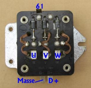
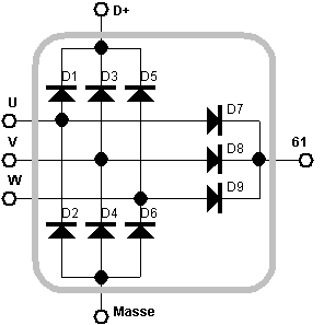
Image B.2-1: Rectifier block (left) and equivalent circuit
(right)
In order to obtain a
rectified voltage that corresponds to the current generator voltage, an additional
rectifier circuit consisting of D7, D8 and D9 leading to connection 61 is
required. There the speed- and load-dependent, rectified generator voltage can
be tapped, the size of which is decisive for the controller for controlling the
excitation current.
As a result, it is
not the voltage at D + that is the controlled variable, but the voltage at
connection 61. This leads to effects such that a load or temperature-related
voltage change at diodes D1, 3, 5 from diode trio D7, 8, 9 at 61 hardly "noticed" and therefore not
corrected. This fact must also be taken into account when troubleshooting. The
controller is not always defective if the voltage values on the
battery are not correct. The rectifier must always be included in the error
analysis.
Dielectric strength of the diodes
The first rectifier modules up to 1986 [2]
contained type SY170 / 1 and SY171 / 1 diodes with only 100V blocking voltage,
so that voltage peaks in the on-board network had to be suppressed with an
additional 2.5 µF capacitor.
The more voltage-resistant variant can be
recognized by the sticker "UR = 200 V". If it has dissolved, you can
recognize them by the 200 V components SY170 / 2 and SY171 / 2. Unfortunately,
both variants have the same spare part number, namely 8046.2-300. If the plate is changed, it must be ensured that the
capacitor is present in the 100 variant. In the case of the 200 V rectifier
module, the capacitor can be removed, but it can also be left without affecting
its function.
It is easily possible to replace a defective
rectifier plate with a modern 3-phase rectifier block for 15 A or more and with
a blocking voltage> 200 V. The auxiliary bridge D7, 8, 9 must then also be
implemented, whereby its current load can be set to be significantly lower
(approx. 5 A).
B.2.2
Function test
The function test of the rectifier block when
it is not connected is limited to the individual test of all rectifier
diodes. Either you use the diode test function of the multimeter or you create
a continuity tester with simple means, as shown in Figure B.2-2.
(a) (b) 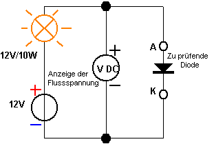

Image B.2-2: (a) Test in forward direction (lamp lights up), display: forward
voltage
(b)
Test in reverse direction (lamp does not light up), display: reverse current
|
|
A node |
K atode |
|
|
|
|
|
D1 |
U |
D + |
|
D2 |
Dimensions |
U |
|
D3 |
V |
D + |
|
D4 |
Dimensions |
V |
|
D5 |
W. |
D + |
|
D6 |
Dimensions |
W. |
|
D7 |
U |
61 |
|
D8 |
V |
61 |
|
D9 |
W. |
61 |
Table B.2-3:
Allocation of the diode connections
In principle, transmission (lamp must light) and
blocking behavior (lamp remains completely dark) must be checked.
The forward voltage (= forward voltage) of each
diode is (0.85 ± 0.15) V at approx. 1 A forward
current (slightly dependent on the battery condition and the power consumption
of the bulb used). The reverse current must be well below 1 mA, typically in
the µA range.
B.3
Electromechanical controller (12V)
B.3.1
Mechanical adjustment
The mechanical adjustment of the 12 V
controller differs in the following points from that of the 6 V controller described in Section A.2.1:
The so-called current limiting contact
is located at the place of the reverse current contact .
According to [2], the contact distances are
Current
limiting contact 1.5 mm
Regulator
contact 0.3 mm
B.3.2
Electrical adjustment
As already explained
in section B.2.1 on the rectifier block, the controller input (61) and the
on-board power supply (51 / D +) must be galvanically isolated from each other
in the 12 V three-phase system, since the Battery voltage is present.
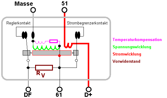
Fig.
B.3-1: Electrical function diagram of the electromechanical controller.
The main current
path from D + to 51 "winds" around the controller core with a large
cross-section only a few times. If the current in the main current path is too
high or if there is a short circuit, the few windings cause the current limiter
contact to open. If the current limiter opens, the field winding can no longer
be supplied with the maximum voltage from 61, but at most via the field winding
series resistor. This at least prevents extreme overloading of the LiMa in the
event of a fault (Fig. B.3-1).
The coil-resistor
combination parallel to the voltage winding is probably a device for
temperature compensation of the controller.
Connection sequence of the electromechanical 12
V regulator:
Ground DF 61 D + 51 ground
Preliminary test of the controller
with the help of resistance measurements
(unused connections remain open)
Before the measurement,
the contacts must be cleaned with a strip of hard, transparent drawing paper
(parchment), otherwise the small contact resistances of 0.4 Ω and less cannot be
detected!
|
element |
Measurement between |
condition |
resistance |
|
Voltage coil |
61 and mass |
|
R SSP (18 ± 2) Ω |
|
Current limiter contact and Controller contact together |
DF and 61 |
Rest position Current limit open Controller contact in Middle position |
0 ... 0.4 Ω R V (8.5 ± 2) Ω R V (8.5 ± 2) Ω |
|
Controller contact |
DF and mass |
pressed on Middle position Rest position |
0 ... 0.2 Ω R V + R SSP (26.5
± 4) Ω R SSP (18 ± 2) Ω |
|
Current winding |
D + and 51 |
|
0 ... 0.2 Ω |
Table B.3-2: Resistance values
on the 12 V
regulator
Electrical adjustment of the
controller
In contrast to the 6
V controller, general operating parameters are given for the 12 V controller in
[2] that can only be checked when installed and with the engine running (see
Table B.3-3).
As with the 6 V
system, concerns about the upper limit of the on-board voltage of 14.6 V (=
gassing limit of the battery at 25 ° C) must be reported, especially since the
voltage information relates to an unspecified point in the on-board network,
i.e. possibly can also refer directly to the battery terminals.
|
Regulated voltage when the LiMa is loaded with 3 A. over the entire speed range |
13.8 ... 14.6 V. |
|
Maximum load voltage when the LiMa is loaded with 15
A, N> 3800 min -1
|
13.0 ... 13.5 V. |
|
Start of current control *) |
11.5 ... 14.0 A |
*) the current
limiter contact starts to work
Table
B.3-3: Information on electrical adjustment from [2]
The following
instructions enable the controller to be checked when it has been dismantled,
so that a statement on the function is possible regardless of the engine
running and the rest of the electrical system.
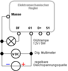
Fig. B.3-4: Circuit for voltage
adjustment
of the controller
contact or function test
Voltage adjustment of the regulator
contact
The voltage of the
controllable DC voltage source is increased slowly and continuously, the
brightness of the incandescent lamp increasing to the same extent. If the
voltage is increased further above 12 V, the lamp suddenly decreases its
brightness a little. When the voltage is reduced, the point at which the light
bulb becomes brighter is reached again. This switching point, which can be
easily limited by carefully varying the voltage, should be around 14.0 V. To
determine the value, an optimal charging voltage of 13.8 V for the battery and
a lead value of 0.2 V for voltage drops across cables and fuses were taken into
account.
If the tension is too low , the bending element must be bent
outwards in order to increase the return force
of the contact return spring.
If the
tension is too high, bend the bending element inwards
.
The on-board voltage
value must be checked or corrected after the controller has been installed (see
Section V.2.3) in order to allow for an adaptation to the special conditions. In
addition to the difficult to predict voltage drops in the on-board network,
there is also the fact that the on-board voltage (51) and the regulator input
voltage (61) are not identical and can differ by a few tenths of a volt (see
explanations in the section on rectifier block B.2.1).
Control of the current limit
The test described
below is actually not advisable because the effort involved in checking the
current limiting function hardly justifies the benefits. Nevertheless, a
proposal should be made for checking outside the on-board network. For a better
understanding, the complete internal circuit of the controller has been shown
(Fig. B.3-5).
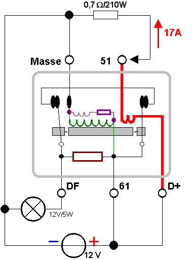
Fig. B.3-5:
Circuit for checking the current limiter contact
An external 12 V
starter or car battery is best used for the test because a very high current is
required for a short time. About the way:
61 -> current limiter contact ->
regulator contact -> DF
the test lamp
receives 12 V operating voltage and lights up.
At 51, the circuit
is briefly closed (caution, high power consumption!) Via a 0.7 Ω resistor. About 17 A flows from D + to 51 through the
regulator. The maximum value of the current at which the limiter contact opens
(see Table B.3-3) is 14 A. Accordingly, it should open with certainty at 17 A
test current, which can be seen from the reduced brightness of the test lamp,
as it is no longer now receives voltage directly, but via the internal
regulator resistor. As a precaution, it should be checked that the loss of
brightness is not caused by a voltage drop in the battery when the current is
high. To do this, briefly contact the positive pole of the battery with the 0.7
Ω resistor,
whereby no loss of brightness should be discernible.
Low resistances for
high loads in short-term operation can be provisionally made from copper wire
(see section V.1.1 "Cable resistances").
20 m Cu line of 0.5
mm 2 results in about 0.7 Ω . A test duration of 1 s or less is sufficient to determine the decrease
in brightness of the test lamp.
Caution: The wire
heats up instantly, so that the insulation is destroyed over a longer period of
time and there is an acute risk of fire.
B.4 Electronic controller (12V)
B.4.1
Replacement of electromechanical by electronic plus regulator
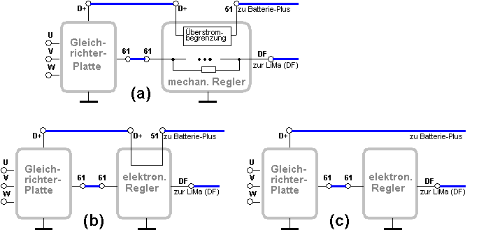
Image
B.4-0:
Comparison of the integration of mechanical (a) and electronic controllers with
(b) or without (c) separate connections for (D +) and (51)
In the instructions
for the installation of commercially available electronic controllers, it is
always required that the field winding series resistor must be removed.
With the 12 V
three-phase systems, this resistance is not in the LiMa, as with
the 6 V systems, but
is located under the base plate of the electromechanical controller. If this
controller is removed, the series resistor is automatically removed and no
further measures are required.
Does the electronic
controller to be used have no separate connections
for D + and 51 (= B
+) on, then D + from the rectifier plate is directly connected to battery
positive
to be connected (Fig.
B.4-0).
12 V three-phase
systems with electromechanical controllers are plus-regulated . The
electronic replacement regulator must therefore also be a plus
regulator .
B.4.2
Function test for electronic (plus) controller
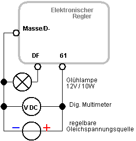
Fig.
B.4-1: Circuit
for the function test
Electronic (plus)
controllers can be checked for function with the circuit specified above (Fig.
B.4-1) when they have been removed (or "disconnected"). This applies
both to commercially available, universally applicable electronic controllers
and to self-made solutions. When the voltage at 61 is increased, the brightness
of the lamp increases to the same extent. When the cut-off voltage is reached
and exceeded, the incandescent lamp goes out in the range of a few tens of mV.
The switching point
for the reduction is determined when the lamp is at medium brightness. It
should correspond to the optimal charging voltage of 13.8V. If you factor in a
voltage drop of a few tenths of a volt across the lines and the fuse, the
cut-off voltage can also be higher by this amount. Cut-off voltages of 13.8 V
... 14.0 V are therefore optimal.
However, as with almost all commercial
electronic controllers, there are no controls for the voltage at the regulator
itself. Emergency is an increase in the voltage by a prescreening ( ³ possible 3-amperes) diode at the
(61) of the regulator. He then quasi "sees" a measurement voltage
reduced by the forward voltage of the diode, which leads to an increase in the
charging voltage at the output of the rectifier plate (D + = 51 = B +) by the
same amount.
The voltage in the main circuit can be
reduced by inserting a ( ³ 15 ampere) diode in front of
the main fuse. Since the entire LiMa current flows through the diode, a power
consumption of up to 15 W must be taken into account when installing.
B.4.3
rectifier / Electronic (minus - ) controller in the last 2T models
In the course of
further development, the controller
circuit (One Chip Car Alternator Regulator) L9480 (manufacturer:
ST.SGS-Thomson
Microelectronics) is used (Fig. B.4-2), which works as a minus regulator. A
detailed description of the properties of the switching regulator L9480 can be
found in Appendix Z.4.
Fig.
B.4-2 : Circuit of
the rectifier-regulator assembly
Schottky diodes were used as rectifier diodes
which, due to their low forward voltage, allow a low power loss and thus a
better degree of efficiency compared to conventional Si-pn diodes
.
The input signal for
the electronic tachometer (DZM) is picked up from one of the three-phase
connections U, V, W. For the function it does not matter which one is used.
Thanks for
information from torbiaz, paule56,
TS-Jens (mz-forum.com)
Left : Conventional variant with right: Electronic rectifier /
electromechanical
controller controller
assembly with electronic
Tachometer
(DZM)
Fig.
B.4-3 : Integration
of the electronic rectifier / regulator assembly into the on-board network of
the ETZ.
Just like the DZM
line, the LKL line (charge control light) is a “hot” connection, as it is
routed unsecured through the vehicle. In the event of a short to ground, not
only are the rectifier diodes endangered, but there is also an acute risk of
fire, as the full LiMa power is behind it. We recommend installing a flying
fuse (500 mA) close to the rectifier / regulator.
In a first variant, the rectifier / regulator
assembly was arranged under the bench instead of the rectifier plate (Fig.
B.4-4).
In the later version, the rectifier controller
board, which is soldered to the winding connections U, V, W, is located in the
LiMa housing (Fig. B.4-5).
Image B.4-4:
Rectifier plate with regulator
circuit L 9489 (Photo: Ysengrin, mz-forum.com)
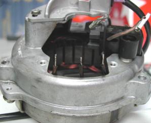
Image
B.4-5:
Rectifier regulator
board on the LiMa LiMa,
G / R board unsoldered and
(Photos: paule56,
mz-forum.com) dismantled
B.4.4
Function test of rectifier / electronic (minus) controller
The rectifier plate
with the regulator circuit under the seat or the rectifier regulator board on
the LiMa must be removed from the vehicle for the test. The circuit board on
the LiMa must be carefully unsoldered from the wire connections U, V, W so that
the conductor tracks and winding ends are not damaged. Since the individual rectifier
diodes should not be unsoldered from the regulator circuit, the function
test is more complex than with the standard rectifier board (see B.2.2); 4
measuring circuits (a) ... (d) are required for this.
If
irregularities occur during the diode tests, the controller circuit still in
the circuit must be included in the investigation as a possible source of
error!
|
|
A node |
K atode |
|
D1 |
U |
D + |
|
D3 |
V |
D + |
|
D5 |
W. |
D + |
|
D7 |
U |
61 / DF + |
|
D8 |
V |
61 / DF + |
|
D9 |
W. |
61 / DF + |
|
D2 |
Dimensions |
U |
|
D4 |
Dimensions |
V |
|
D6 |
Dimensions |
W. |
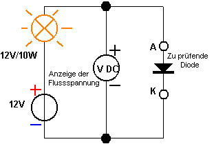
Figure
and Table B.4-6: Testing in the forward direction (a)
In test step (a), all diodes are tested in the
direction of flow. The forward voltage of the Schottky diodes used is 0.4 ... 0.5
V. If voltage values close to zero volts or greater than 1 V are
displayed, it is very likely that the corresponding diodes have failed.
|
|
A node |
K atode |
|
D1 |
U |
D + |
|
D3 |
V |
D + |
|
D5 |
W. |
D + |
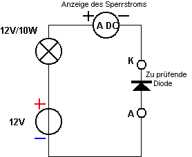
Figure
and Table B.4-7: Testing in the blocking direction (b)
D1, D3, D5 can be
tested in test step (b) in the known standard circuit in the reverse direction.
Normally the reverse current is below 1mA, typically it is only a few µA or
even less. The additional connection after connection (61) or ground in test
steps (c) and (d) is required to divert the operating current of the regulator
circuit. If the connection is omitted, the multimeter shows the operating
current of the L9480 regulator circuit (approx. 20 mA) instead of the reverse
current of the diodes.
|
|
A node |
K atode |
|
D2 |
Dimensions |
U |
|
D4 |
Dimensions |
V |
|
D6 |
Dimensions |
W. |
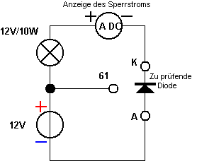
Figure
and Table B.4-8: Testing in the blocking direction (c)
|
|
A node |
K atode |
|
D7 |
U |
61 / DF + |
|
D8 |
V |
61 / DF + |
|
D9 |
W. |
61 / DF + |
Figure
and Table B.4-9: Testing in the blocking direction (d)
For the controller
test (circuit L9480), set up the circuit as shown in Figure B.4-10. The
procedure is identical to that described in Section B.4.2.
Image
B.4-10: Circuit
for function test
B.5 Ignition system (12V)
B.5.1 Contact ignition system
The contact ignition
system for 12V vehicle electrical systems does not differ in principle from the
6 V system. In this respect, the sections
A.4.2 Contact, ignition capacitor
A.4.3 Ignition coil
A.4.4 Ignition cable, connector and plug
V.7. The setting of the breaker ignition
with regard to fault
diagnosis, testing and maintenance. The ignition coil
for 12V only has different resistance values. Unfortunately, only a single coil
was available to limit these parameters, so the measured values
do not necessarily have to be typical (see Table B.5-1).
|
element |
Measurement between |
resistance |
|
|
|
|
|
Ohmic resistance of the primary coil |
(1) and (15) |
(4.5 ± 0.5) Ω |
|
Ohmic resistance the secondary coil |
(15) and K |
(8.5 ± 1) kΩ |
|
Insulation resistance |
(1) and housing such as (15) and housing such as K and housing |
> 1 M Ω each |
Table
B.5-1: Winding
and insulation resistances of the 12 V ignition coil
B.5.2
Electronic ignition system with Hall sender
(1)
"Hermsdorfer MZ ignition"
The electronic
ignition system consists of the transmitter unit attached to the crankshaft
with the Hall element (= sensor sensitive to magnetic fields) and the remote
signal processing unit.
Fig.
B.5-2: Encoder unit
with removed Fig. B.5-3: Equipment side of the
menem permanent ring
magnet signal processing unit
(Photo: Voodoomaster, mz-forum.com)
 Fig.
B.5-4:
Encoder unit Fig. B.5-5: Signal processing unit
Fig.
B.5-4:
Encoder unit Fig. B.5-5: Signal processing unit
Function test of the encoder unit
First the connection
cable is checked for continuity from the blade terminal to the board solder
point. The function of the Zener diode is then tested as shown in Fig. B.5-6;
the voltage between 15g and 31g must be 4.75… 5.25 V. If it is above 7
V, the Zener diode is defective. Since it is soldered onto the conductor track
from above (see Figure B.5-2), it can be replaced, but problematic because of
the solid potting compound. It is easier to leave the defective diode and add a
5.1 VZ diode on the board of the signal processing unit (between (15g) and
(31g)).
If the Zener diode
was defective, it may be that the sensor circuit has already been destroyed due
to the impermissibly high voltage at pins 3 and 4, which can be found out with
the help of the switching test described below. If a more voltage-resistant
circuit B462 (operating voltage 4.75 ... 18 V) is used, the 5 VZ diode is still
required because the internal input pin 3a maximum of 5.5 V may be applied to both circuit
variants. If the ring magnet is turned, the 12 V LED lights up over an angle of
rotation of 180 ° if the encoder is intact and remains dark for the following
180 °. This means that the transmitter function can be verified at least
statically. However, after a successful static test, it is unlikely that
malfunctions will occur in dynamic operation at higher speeds.
Fig.
B.5-6: Circuit for
the function test of the encoder unit
Fig.
B.5-7: Circuit for
the function test of the signal processing unit
Function test of the signal
processing unit
In the test circuit
shown in Figure B.5-7, the 12 V / 21 W bulb is used to simulate the load on the
ignition coil. If the transmitter unit switches "on", the potential
at (1) is drawn down to approx. 1 V residual voltage against ground and the
light bulb lights up. This is achieved by connecting the terminal (7) to ground
(31g or 31) with a wire bridge. If (7) is open again, the light bulb must not
light up. If the incandescent lamp lights up continuously or remains dark,
there is a fault in the signal processing unit of the electronic ignition
system.
(2) "PVL / MZ ignition"
Hall sensor and signal processing unit of the PVL / MZ ignition are in
a red or black cast function block directly on the LiMa (Fig. B.5-8).
Image
B.5-8:
Electronic PVL / MZ ignition (Photo: Welu, mz-forum.com)
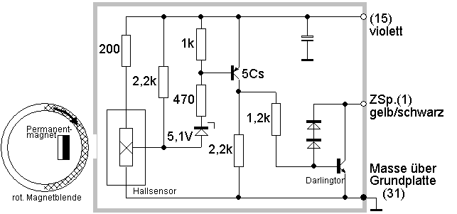
Fig.
B.5-9: Circuit of
the electronic PVL / MZ ignition
The PVL ignition can be statically tested in the removed state analogous to the test circuit shown in
Figure B.5-7. On the input side, however, actuation takes place by moving a
thin sheet of iron past the sensor as a magnetic screen. If the unit is intact, a switching process
occurs (lamp on / off). As with the Hermsdorfer ignition described above, a
residual voltage of approx. 1 V remains at terminal (1) in the on state.
A disproportionately high expenditure of special electronic measuring
technology is required to prove frequently described, probably thermally caused
failures, so that it cannot be discussed here.
Thanks to IFArista, mz-forum.com for providing the analysis sample C permanent magnet 12V three-phase
generator (Rotax)
C.1 Three-phase generator - function test
As with the
field-regulated three-phase generator, the stator contains the voltage
induction coils. Instead of the excitation field coil, however, a rotating
permanent magnet - similar to a bicycle dynamo - is arranged. The generator
voltage can therefore not be influenced via the excitation field as with the
field-regulated three-phase generator (Chapter B). The faster the rotor turns,
the greater the generator voltage becomes. We are used to it in the same way
from conventional bicycle dynamos.
The stator winding
and rotor are designed in such a way that 6 full sine periods are generated on
each of the phases U, V and W per crankshaft revolution (see diagram in Figure
C.1-1). This relationship is important for the signal generation of electronic
tachometers, which are clamped to a phase line of the LiMa.
Fig.
C.1-1: Block diagram
of the 12 V / 190 W permanent magnet three-phase LiMa
and
Voltage
of a LiMa phase in relation to crankshaft rotation
If a fault is
suspected in the LiMa, the winding resistances should first be checked in order
to detect winding shorts / interruptions or insulation problems. In [4],
different resistances or ranges are specified for the individual three-phase
windings, which were only partially confirmed in an exemplary test measurement
on an intact vehicle. The resistance of all three strands was uniformly 0.7 Ω when measured on a vehicle
|
element |
Measurement conditions |
Measurement between |
resistance
|
|
|
|
|
|
|
Three-phase windings |
Cable from Connector strip deducted |
white and orange white green green orange |
0.6-0.9 [4], own measurement 0.7 Ω 0.54-0.8 Ω [4], own measurement 0.7 Ω 0.8-1.6 Ω [4], own measurement 0.7 Ω |
|
isolation |
dito |
white and ground green and ground orange and ground |
> 1 M Ω, typically
over 20 M Ω |
Table
C.1-2:
Winding and insulation resistances of the Rotax LiMa
If the resistance
measurement (see Table C.1-2) does not reveal any abnormalities, the LiMa can
be tested with an equivalent load (Figure B.1-4). For this purpose, three 60 W
headlight lamps are connected to the three-phase connections U, V, W (or cable
colors white, green, orange) as shown in Fig. C.1-3, the controller remains
disconnected. It would be safer to use 24 V lamps, if available, as the
alternating voltage already reaches 12 ... 14 V at idle speed. The speed must
therefore never be increased! The headlight lamps must shine brightly.
Fig.
C.1-3: LiMa test
circuit 
If power resistors
12 Ω /
≥60 W are used instead of incandescent lamps, the speed can be briefly
increased to 3000 min -1 . The alternating voltage reaches a
value of approx. 27 V ~ (measure at U, V, W one after the other),
whereby a power of approx. 180 W is drawn from the LiMa .
C.2 Rectifier / regulator block - function test
The Rotax regulator is
a block that contains the usual three-phase bridge rectifier (circuit similar
to Fig. B.2-1, but without diodes D7-D9) and 3 thyristor switches (for a
detailed circuit see Appendix Z.2). When the target DC voltage is reached at
the output (black cable), the individual (yellow) three-phase connections are
short-circuited to ground by thyristors for the duration of one or more voltage
half-waves, so that the output voltage remains at the target value and cannot
increase any further.
Fig.
C.2-1: Connections
on the rectifier / controller block. The three-phase connections (yellow) are
basically interchangeable and are therefore not differentiated on the
controller block
The test of the
rectifier function is completely analogous to the test of the rectifier
block in section B.2. The conduction (a) and blocking behavior (b) of the
individual internal rectifier diodes must be checked as shown in Figure C.2-3.
|
A node |
K atode |
|
|
|
|
U |
B + |
|
Dimensions |
U |
|
V |
B + |
|
Dimensions |
V |
|
W. |
B + |
|
Dimensions |
W. |
Fig.
C.2-3: Diode test Table
C.2-2:
(a) Test in the
forward direction (lamp lights up), connection
diagram
Display: forward
voltage
(b) test in reverse
direction (lamp does not light up),
Display: reverse
current
The forward voltage (=
forward voltage) is (0.85 ± 0.1) V
at approx. 1 A forward current (depending on the battery status and the power
consumption of the light bulb). The reverse current must be well below 1 mA,
typically in the µA range.
The function of
the thyristor switch can be checked by connecting a controllable DC voltage
source to the three-phase current connections via a 12 V / 10 W light bulb as
shown in Fig. If the voltage of the source is increased slowly, you will find a
switching point at around 14 V at which the lamp suddenly starts to glow and at
the same time the voltage display at B + jumps to zero. If the voltage of the
source is now reduced again, the lamp continues to glow, but becomes darker as
the source voltage is reduced. A new switching attempt can only be started
after the lamp has been briefly disconnected from the three-phase connection.
Fig.
C.2-4: Test of the internal thyristor switching function
Switching points
determined in practice at B + for three controller copies at U, V, W were:
13.95 V-13.89 V-13.96 V;
13.96V-13.97V-13.96V;
13.96V-14.23V-13.96V
Based on the example
measurements, you can expect values in the range of 13.7 ... 14.4 V with
a perfect controller.
C.3 Electronic tachometer (eDZM)
The input of the eDZM with the type designation 12 P VCC 12 is connected to one of the
three three-phase phases (U, V, W) coming from the LiMa. According to the
repair instructions [8], p. 38, that phase must be selected for the connection
which “is live in every operating state
of the charging system”. To find out, the engine should run, the battery
should be fully charged and no other loads should be switched on. All three
phases are probed one after the other with an alternating voltmeter. At the
phase "which carries voltage, the
signal cable comes green".
The above procedure is functionally
incomprehensible. In practice, all three strings U, V, W carry voltage that is
more or less subject to the phase control of the switching regulator. It will
never be the case that only one phase is live and the remaining two are
completely switched to zero. At best, you will find a phase whose tension is
greater than that of the other two, because it is not at all or less often
compared to the other two. If you select this, however, it is not guaranteed
that with longer journeys and higher engine speeds it will also be cut in or
cut away over more or less periods. As is well known, this leads to incorrect
display values or chaotic fluctuations in the display.
That is why there
were changes about a year after the start of series production. The eDZM of the
type 12 P VCC 2, which has been used
since 1992, is now connected to the blue wire from the ignition sensor to the
ignition box. This provides a stable input signal with speed information for the eDZM. Both eDZM
types are not interchangeable! The 12 P
VCC 2 can, however, be built into the older Rotax models, whereby its input
has to be connected to the blue wire from the ignition box mentioned above.
More information on
the functioning of the electronic DZM used by MZ can be found in Section V.6.
C.4 Electronic ignition (CDI, Nippondenso)
The ignition of the
Rotax engine 504E works according to the CDI process ( C ondensor D ischarge I
gnition = capacitor discharge ignition). The capacitor contained in the
amplifier box is charged by two charging coils located in the stator, the lower
one in Figure C.4-1 being effective at low speeds and the upper one at higher
speeds. The ignition point is determined by two transmitter coils, with the
external sensor realizing an ignition angle of 3 ° before TDC at low speeds and
the internal sensor at high speeds up to 29 ° before TDC.
If the stop switch is operated, the internal
capacitor is short-circuited and the ignition spark is instantly eliminated.
Fig.
C.4-1: Connections
of the CDI ignition box (amplifier box, Nippondenso 070000-0780)
Fig.
C.4-2: Pin
assignment on the amplifier box
According
to the repair manual for the Rotax motor [4] p. 45, testing the amplifier box
is limited to measuring the resistance between all completely disconnected
cable connections. If input elements are "shot", you will find out with
them. However, this method is not a 100% functional test.
The
resistance matrix given in [4] is flawed in that plus and minus were swapped in
the matrix on page 45. On the other hand, a contemporary ohmmeter is required
(the motor went into series production around 1980) that works with an external
test voltage of> 2 V in order to be able to test diodes in the direction of
flow. This was usually the case with the pointer instruments of the time
without electronics. Nowadays, modern multimeters often work with voltages
below 0.5 V at the measuring sockets, so that there are displays that do not
have to coincide with those in the matrix specified there.
Suitable
test equipment with which the test can still be carried out nowadays are
a)
Multimeters that deliver a voltage of at least +2 V to the measuring sockets in
the resistance measuring range (20 kΩ) or in the "Diode test" operating mode (if
available) (checking by direct voltage measurement with a second multimeter is
possible) or
b) the test
circuit according to Figure C.4-2
When
testing with a test lamp, however, it must not happen that the connections of
the amplifier box inadvertently come into direct and simultaneous contact with
the plus and minus pole of the battery, as this would destroy internal
components. Test lamp outputs greater than 2 W can also be harmful.
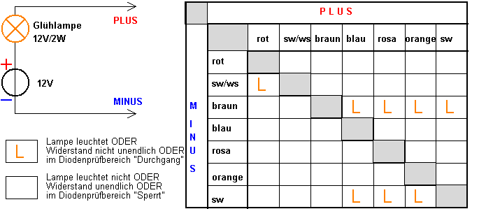
Fig. C.4-2: Test equipment for testing the amplifier box and the associated test
matrix
If the amplifier box
is unplugged, the winding resistances of the charging, transmitter and ignition
coils can also be checked in order to determine breaks in the windings or short
circuits to ground (see [4] p. 44). According to Fig. C.4-1, it must be ensured
that the ground connection of the external transmitter coil is not connected to
the other ground connections when it is disconnected.
The cable colors
pink - orange - brown are not always easy to distinguish, especially when they
are dirty. It is therefore imperative to clarify this before taking
measurements.
The internal
circuitry and function of the amplifier box are explained in more detail in
Appendix Z.3.34.
V Miscellaneous
V.1
Cable connections
V.1.1 Cable resistance and voltage drop
The resistance
between the two end connection points is decisive for assessing the quality of
a cable connection. Since these resistances are usually less than 100 m Ω , an exact direct measurement with simple
digital multimeters in the resistance measuring range is hardly possible.
|
Copper
cross-section |
length-related
resistance |
Voltage drop for 1m and 10A
current |
|
|
|
|
|
6 mm 2 |
2.9 mΩ / m |
30 mV |
|
4 mm 2 |
4.4 mΩ / m |
40 mV |
|
2.5mm 2
|
7.0 mΩ / m |
70 mV |
|
1.5mm 2
|
11.7 mΩ / m |
120 mV |
|
1 mm 2 |
17.5 mΩ / m |
180 mV |
|
0.75mm 2
|
23.3 mΩ / m |
230 mV |
|
0.5mm 2
|
35.0 mΩ / m |
350 mV |
Table
V.1-1: Cable
resistances and voltage drops for different cross-sections
It is therefore more
practical to measure the voltage drop across the cable connection when the test
current is known, since even simple digital multimeters offer a sufficiently
accurate voltage measurement in the mV range.
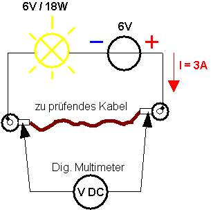
Fig.
V.1-2:
Measuring circuit for cable voltage drop
The measuring
circuit according to Figure V.1-2 is variable with regard to the impressed current,
which is determined by the battery voltage and the power consumption of the
incandescent lamp. In this example, a 6 V / 18 W incandescent lamp and a 6 V
battery are used, which gives about 3 A test current through the cable, which
is precisely determined with the multimeter before the actual measurement. The
voltage drop is now tapped with the multimeter within the two feed points (in
the example cable clamps with eyes) so that the voltage drops are not recorded
directly at the feed points.
Measurement
example:
Cross section of the
cable to be tested 0.75 mm 2 , length 1.3 m
Resistance per meter according to table V.1-1:
23.3 m Ω / m.
Resistance for 1.3
m cable length: 23.3 mΩ / m *
1.3 m = 30.3 m Ω
Expected voltage
drop for 3 A: U
= I * R = 3 A * 30.3 mΩ = 91 mV
Assuming the practicable test accuracy of 10%
, a measured value in the range of 80 ... 100 mV would be expected. If
the voltage drop exceeds the maximum value by more than 50%, there is very
likely a cable fault.
V.1.2 Voltage drops in the vehicle electrical system
Voltage drops in the
6 V electrical system with conventional breaker ignition are particularly
critical; it is worthwhile to identify neuralgic points. Intermittent ignition
at idle speed and / or when the headlight is switched on are usually a sign
that the voltage effective on the ignition coil is significantly lower than the
terminal voltage on the battery. Causes are partial voltage drops via cable and
plug connections, fuses, ignition light switches and the breaker contact.
The systematic
investigation is based on the schematic circuit shown in Fig. V.1-3. The
procedure outlined below can also be transferred to 12 V systems or other areas
of the vehicle electrical system.
Before the
measurement it is ensured that
that the measuring points A to L are freely
accessible,
that the lower cup contact is closed and
that the battery is OK and fully charged.
It is advisable to measure in the 2 V DC voltage measuring range of the
digital multimeter, since the voltages are only a few tenths of a volt.
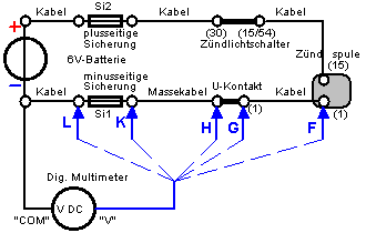
(a) (b)
Fig.
V.1-3: Complete
ignition circuit for determining the partial voltage drops
(Explanation: H:
base plate of the U-contact, G: contact lug on the capacitor)
Starting with the plus side (a) of the circuit according to Fig. V.1-3,
the "V" socket of the digital multimeter is firmly connected to the
plus pole of the battery via the plus measuring cable. The measuring points A
to E are scanned one after the other with the minus measuring line ("COM"
socket). The test tip is placed safely and firmly on the respective measuring
point. The ignition and the light are switched on briefly for the
measurement . Since the battery is loaded with around 10 A at this moment
(headlights, taillights, ignition coil), 1 ... 2 s must be sufficient for
reading. The measured value is entered according to the example in Table V.1-4.
The measurements on the minus side (b) according to Fig. V.1-3 are carried out
analogously. Finally, the differential voltages are calculated in the table.
In order to obtain reproducible results, the
battery voltage should remain as
constant as possible during the measurement (check with a multimeter). The
battery voltage usually recovers in short pauses between measurements, and
recharges if necessary.
If the differential voltages are more than 50%
above the typical values given in Table V.1-4, improvements must
be made to the corresponding elements (check cables and cable connections as
well as plug-in forces, clean contacts, maintain U-contact, check fuses and
fuse contacts) .
Improvements can generally be achieved by
increasing the cross-section of the cable connections. It is also advantageous
to solder the cable connections (flat connectors, eyelets) or to re-solder
existing crimp connections in the entire circuit A to L. The ignition light
switch has several contact lugs (15/54), exchanging the slots may lead to an
improvement. The conversion from torpedo to flat fuses is recommended.
The sum E + F (voltage loss over all) indicates
how much lower the voltage applied to the ignition coil is compared to the
terminal voltage on the battery; a value below 800 mV = 0.8 V should be aimed
for.
Measuring Point |
Voltage in mV |
|
Diff. Voltage in mV |
Responsible element
|
|
|
|
|
A. |
24 |
Cable connection from battery positive to the plus fuse Si2 |
|
|
A. |
24 |
|
|||
|
BA |
95 |
Plus fuse Si2 including fuse contacts |
|
||
|
B. |
119 |
|
|||
|
CB |
73 |
Cable connection from Si2 to the ignition light
switch (30) |
|
||
|
C. |
192 |
|
|||
|
DC |
111 |
Ignition light switch between (30) and (15/54) |
|
||
|
D. |
303 |
|
|||
|
ED |
55 |
Cable connection from the ignition light switch
(15/54) to the ignition coil (15) |
|
||
|
E. |
358 |
|
|||
|
|
|
E + F = voltage loss over everything: 640 mV |
|
||
|
F. |
292 |
|
|||
|
FG |
31 |
Cable connection from U-contact to the ignition coil (1) |
|
||
|
G |
261 |
|
|||
|
GH |
90 |
U contact |
|
||
|
H |
171 |
|
|||
|
HK |
52 |
Ground cable from Si1 to the ground connection in the alternator |
|
||
|
K |
119 |
|
|||
|
KL |
95 |
Minus fuse Si1 including fuse contacts |
|
||
|
L. |
24 |
|
|||
|
L. |
24 |
Cable connection from battery minus to the minus fuse Si1 |
|
||
|
|
|
|
Table
V.1-4:
Exemplary measurement protocol with averaged measurement values
of three
Vehicles (ES150, ES150 / 1, ES175 / 2). The
vehicles were with
Flat car
fuses and some larger ones with cables
Cross-section
equipped.
The differential voltages can also be measured
directly, as shown in the example in Fig. V.1-5. This method is recommended if
the success of improvements to a certain element is to be tracked by
measurement.
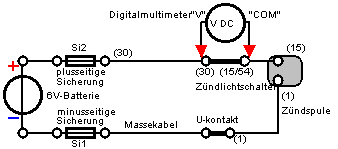
Fig.
V.1-5: Differential
voltage drop across the ignition light switch
V.2 accumulator (lead battery)
V.2.1 Characteristic values and
properties
The battery is the
most sensitive, capricious and most difficult to see through creature in the
vehicle, which is why this section on its properties is also quite long. If you
are only interested in subjecting your battery to a function test, you can
confidently jump to Section V.2.2.
Since the lead acid
battery is still most frequently used in the vehicle sector, all information
and tests refer to it. Much of this, however, can also be transferred to other
battery systems - eg NiCd - in the same way.
An accumulator
, known colloquially as a battery, stores electrical energy in a chemical way. The
lead battery contains sulfuric acid as an electrolyte. In contrast to the
primary battery, it can be repeatedly discharged and charged.
Its most important
parameters are nominal voltage [V] , nominal capacity [Ah] and internal
resistance [m Ω ].
The prefix "nominal"
means that the properties are intended for the design, in contrast to this,
"voltage" and "capacity" denote the current, available
values that a particular specimen has at the moment, i.e.
depending on the state of charge, Temperature or age.
The term capacity
refers to the battery capacity for electrical charge. The battery capacity thus
indicates in an idealized way the maximum current [A] that can be drawn from
the battery over how many hours [h].
Example: With 6
Ah it is ideally 1 A over 6 h or 0.6 A over 10 h or 2 A
over 3 h etc., the product of current and time always results in 6 Ah.
When the battery is
intact, the voltage drops to a constant value a few hours after the end of the
charging process, the no-load voltage . If, for example, the vehicle was
parked overnight, the no-load voltage can be measured the next day before
starting the journey. The open circuit voltage and other significant voltage
values for lead batteries can be found in Table V.2-1. With fresh
batteries, the value for the open circuit voltage can be up to 5% higher than
specified.
The (maximum)
charging voltage must always be sufficiently below the gassing limit
. As can be seen from Table V.2-1, the margin of around 4% is very small.
The maximum charging
voltage at room temperature (25 ° C) is 6.9 V or 13.8 V for the 6 V or 12 V
lead-acid battery.
It is wrong to
assume that a full battery could be charged further by increasing the charging
voltage above 6.9 V or 13.8 V. Because the battery plates have already been
completely chemically converted, the flowing current only leads to more intense
electrolytic splitting (gassing). Exceeding the maximum charging voltage - true
to the motto "a lot helps a lot" - is often the cause of an
abnormal shortening of the battery life .
|
Values for 25 ° C |
single cell |
6 V battery |
12 V battery |
|
Gassing
limit |
2.40V |
7.20V |
14.4V |
|
maximum charging voltage |
2.30V |
6.90 V. |
13.8V |
|
Rest tension, for example |
2.10 V |
6.30 V |
12.6V |
|
Minimum voltage |
1.87V |
5.60V |
11.2V |
|
Deep
discharge limit |
1.75V |
5.25V |
10.5V |
Table
V.2-1: Important voltage values of the
lead battery at room temperature [3]
With the currently
available rechargeable batteries, a very weak gas development (quiescent
gassing) can sometimes be observed even in idle mode. If the battery has
remained unchanged for a long time and if you tilt it to the side, you can see
or hear gas bubbles rising. The reasons for this phenomenon are unclear, but it
is obviously not of concern. Above
the gassing limit, an electrolytic cleavage reaction with very violent gas
development (oxygen + hydrogen) occurs compared to the weak quiescent gassing.
The internal
resistance indicates how much the battery voltage drops when power is
drawn. The smaller the internal resistance, the lower the terminal voltage
drop.
Example: A
battery has a current terminal voltage of 6.47 V. Its internal resistance
wasspecifiedas 45 mΩ. When
connecting a consumer that draws 10 A, the terminal voltage of the battery
drops by 45mΩ · 10 A = 450 mV, ie the terminal voltage is only
6.02 V.
In order to conserve
the battery, the charging current in A should not be greater than 1/10 of
the Ah number , whereby this should be interpreted as a rough rule of thumb
with leeway. At a
11 Ah battery, for
example, the charging current should not exceed 1.1 A. This rule can only be
complied with with a convenient charger that has a current limiting function,
but not in the vehicle. If the battery is heavily discharged, the regulator in
our MZ will take care of it a waste, because it is a constant voltage
regulator . If the battery is heavily discharged (eg "overnight stay"
with parking light), the charging voltage (see table V.2-1) is effective from
the first moment and a multiple of the recommended maximum charging current
usually flows! Fortunately, this condition often lasts only a few seconds or
minutes. Then the chemistry inside ensures that the electricity returns to
bearable areas. One should know this, however, because one observed from time
to timeInexplicable fuse death immediately after starting the journey
can be caused by a severely discharged battery.
The battery is never
lower than to the minimum voltage that almost 7% greater than the total
discharge border is located , to be operated. A discharge to the
deep discharge limit already nibbles considerably on the battery life, a
discharge below the deep discharge limit can lead to the instant (chemical)
destruction of cells. It is advisable to stay well above the minimum voltage,
because the condition applies to every single cell connected in series (at 6 V
three, at 12 V six), which are not individually accessible and controllable. It
could then possibly go something like: "The lake was a meter deep on
average, but the cow drowned ..."
The polarity
reversal a cell can be fatal for a battery, usually it loses
noticeably in capacity or is a case for disposal. How can it come to that? In
the course of a battery life, the individual cells can age differently, ie the
cell capacities are then no longer the same when charged. Let us assume that 5
cells still have 5Ah, the sixth has always been neglected with regard to its
fluid level and has "aged" down to 3 Ah. If this 12 V battery is now
loaded, the same discharge current flows through all cells connected in series.
If the healthy - let's assume - have now delivered 3 Ah, they still have 2 Ah
"on top", but our problem cell is already empty, because it only had
3 Ah. If the discharge current continues to flow,if it is discharged below its
deep discharge limit, its cell voltage approaches zero. Externally, this can go
unnoticed so far, as her 5 sisters may still bring 5 * 2.2 V = 11.0 V to the
external connections. If the discharge current continues to flow through all 6
cells as before, the cell voltage of the battered cell begins to reverse
polarity. The chemical reactions change the material structure of the plates
and primarily cause a strong increase in the internal resistance of the killed
cell. This appears to the outside in such a way that if the battery charging
voltage is correct, only a very small charging current flows, which signals an
alleged full charge. When loaded, the terminal voltage of the battery collapses
immediately to well below 12 V. The battery is simply dead,resuscitation is no
longer possible.
All characteristics
of the battery, including the voltage characteristics, are temperature-dependent.
A mean value of -4 mV / K for the temperature curve of the charging voltage
per cell results from various sources [3]. Gassing and deep discharge limits
change in a similar way.
|
optimal Charging voltage in V Battery temperature |
cell |
|
6 V battery |
12 V battery |
|
40 ° C |
2.24 |
|
6.72 |
13.44 |
|
25 ° C |
2.30 |
|
6.90 |
13.80 |
|
10 ° C |
2.36 |
|
7.08 |
14.16 |
|
-10 ° C |
2.44 |
|
7.32 |
14.64 |
Table
V.2-2: Optimal charging voltage depending on the temperature
Important
conclusion:
F ÜR the predominant summer
operation, the charging voltage should be two and four tenths of a volt set
lower than 25 ° C (that is, 6.7 V and 13.4 V), then it is in the
bathing weather period on the safe side and reaches in any case the fatal
gassing limit! Of course, this is only possible if the controller has a setting
option.
Fleece and gel
batteries differ in their structure from the usual liquid batteries
in that the sulfuric acid is absorbed in glass fleece mats (fleece) or bound in
silica (gel). Unfortunately it has become common in popular usage to
incorrectly refer to the fleece battery as a gel battery. Fleece and gel
batteries are maintenance-free (leak-proof) and can usually be operated in any
position. The gel battery has a higher internal resistance than the fleece
battery, which is why it is less suitable as a starter battery. The low self-discharge
rate of the maintenance-free batteries should be emphasized , which
predestines them for use in "winter dormant" and little-moving
oldtimers.
Example data for
fleece battery VISION CP450 (6 V / 4.5 Ah)
all information on
the technical data was taken from [6]
Installation
position: any
Measurement
condition for capacity: 1/20
of the Ah number, ie at I = 0.225 A.
Max.
Charging current: 1.8
A
Max.
Discharge current: 67.5
A for 5 s
Self-discharge
rate at 20 ° C: approx. 3% per
month
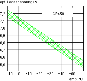
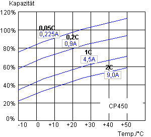
Fig.
V.2-3: Optimal charging voltage Fig. V.2-4: Capacity
as a function of
depending on the
temperature, temperature
and discharge current
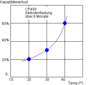
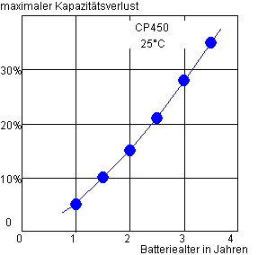
Fig.
V.2-5: Loss of capacity due to Fig. V.2-6: Maximum
capacity
Self-discharge over 6 months loss due to aging
Nominal capacity and
available capacity
At the beginning of
this section it was already pointed out that the nominal capacity of a battery is only a constructively intended
value. This value is usually part of the trade name or printed on the housing
of the battery.
However, the
currently available capacity depends
on several factors such as the state of charge, temperature, battery age and
the size of the load current.
In order to enable
comparability when handling batteries with different nominal capacities, the
load or charging current is expediently related to the nominal capacity. Replacing
the unit of measurement Ah with A results in 100% current. In the above
example, a 100% load on the 4.5 Ah battery corresponds to a current drain of
4.5 A. This is also symbolically written as 1C (1 corresponds to the factor 1,
i.e. 100%; C of current = current). 0.05C would then be 0.225A or 2C would mean
9A.
In this respect, it
is sufficient, for example, to state that the optimal charging current for
lead-acid batteries should be 0.1C. The specific value can easily be calculated
based on the nominal capacity. 1
)
Diagram V.2-4, which
shows the dependence of the available capacity on the load current and
temperature, can therefore also be used as a good approximation for other
nominal capacities.
Example
calculation: A battery has a nominal capacity of 11 Ah and it is 3
years old. What capacity is available after a full charge with a constant load
current of 11 A and an ambient temperature of 0 ° C?
The age of the battery reduces the available
capacity according to diagram V.2-6 by 28%, ie about 11Ah - 28% = 7.9Ah.
A load current of 11A corresponds to the 1C
characteristic curve in diagram V.2-4 and this results in a capacity drop to
45% at 0 ° C, ie 7.9Ah * 0.45 = 3.5 Ah.
Result: Under
the specified conditions, the fully charged
11 Ah battery only 3.5 Ah available.
1 ) In other
representations, an I symbol with an index is sometimes used instead of the C
symbol (e.g. 0.1C = I 10 or 0.05C = I 20 etc.)
V.2.2 Function test
Determination
of the rest voltage
The battery to be tested is charged with the
available charging technology in accordance with regulations and to the best of
our knowledge and belief. The voltage at the battery terminals is occasionally
measured during the charging process. 6.9 V or 13.8 V must not be exceeded at
room temperature (see Table V.2-2) in order to remain below the gassing limit.
After charging and disconnecting from the
charger, the battery is left to its own devices for at least 2 hours or, better
still, overnight. The rest voltage is then measured. If it is 6.3 V or 12.6 V
or more, that's okay. Values below this usually indicate advanced
aging.
With 5.9 V or 11.9 V or less, the battery can
hardly be used.
Determination of the capacity
It is actually not possible to determine the
capacity of a battery without knowing and complying with the conditions
specified by the manufacturer specifically for its product.
However, in order to still determine a
reference value, reasonable measurement conditions are given as follows:
Carried out at room
temperature 25 ° C
1. Full charge
2. Rest for a few hours or overnight
3. Determination of the discharge time at
Discharge current in A of one
twentieth of the number of ampere-hours (0.05C) and
up to a final voltage of 5.6 V or
11.2 V (see Tab. V.2-2)
The capacity then
results from the product of the (mean) discharge current in A and
the discharge time
in hours.
Example: 12 V
battery, nominal capacity 14 Ah
Discharge current
0.05C -> 0.7 A
Discharge power: 0.7
A * 12 V = 8.4 W.
Approximate
realization with available incandescent lamps: 5 W + 2W + 1.2 W = 8.2 W
The lamps are
connected and from that moment the time starts running.
It is advisable to
measure and register the falling battery voltage every hour.
When 12.0 V is
reached, the actual discharge current I (eg 0.65 A) is measured and noted.
If the terminal
voltage has dropped to 11.2 V, the discharge is aborted and the time is stopped
(eg 17 h).
The current capacity
of the battery is therefore 0.65 A *
17 h = 11.05 Ah
The measured
capacity value allows the assessment of the continuous load capacity of the
battery at room temperature. If the capacity falls below 50% of the nominal
capacity, a replacement should be considered. The capacity value is heavily
dependent on the specific conditions such as temperature, size of the discharge
current and battery age; the applicable tendencies can be read off from the
diagrams V.2-4 and V.2-6.
Determination of the internal
resistance
In addition to the terminal voltage value (open
circuit voltage) and the capacity - especially in vehicles with an electric
starter - the internal resistance is decisive for the usability of a
battery . The voltage and capacity may still be OK, but when the button is
pressed, the electric starter can be quite weak. The very high current
of a few 10 A required for a short time during the start-up process causes a
voltage drop through the aging-related increase in internal resistance of the
battery, which greatly reduces the external terminal voltage. The battery can
perhaps be used for other purposes, but no longer as a starter battery. With the kick
starter vehiclesInitially, only energy is required to operate the ignition.
The maximum power consumption with the ignition switched on is around 4 A (6 V
system) or 2.5 A (12 V system). In this case, a moderately increased internal
resistance is less critical, the batteries can be used significantly longer
under the circumstances.
To find out
something about the internal resistance-related age of the battery, we
can measure the voltage difference for "ignition on" / "ignition
off". Of course, this only works in vehicles with battery ignition, where
the current specified above (4 A or 2.5 A) is drawn from the ignition coil.
The "on" /
"off" interplay occurs every second until a stable voltage difference
is established. This should not be greater than 0.3 V (6 V system) or 0.5 V (12
V system), which corresponds to 75 m Ω or 200 m Ω . It
makes sense to do this test once a year (e.g. before the winter break) and to
note the voltage difference. The increase in this difference as the battery
ages is a good indicator of the remaining capacity. The voltage measurement
must take place directly at the battery terminals!
A headlight bulb , for example, can be used
to measure the internal resistance of the battery outside the vehicle . You
connect the light bulb, wait about a minute until the battery voltage has
dropped to a stable value U1 and then interrupt the circuit, whereby the voltage
immediately jumps to a higher value U2. The load change should be repeated
every second until the voltage differences U2-U1 remain stable. Finally, the
lamp current I is determined.
The internal
resistance R i must then be calculated as follows and is preferably
given in mΩ because
of the small number of measurements:
R i =
(U2-U1) / I.
V.2.3 Check operating conditions in the vehicle
electrical system
3 Measurements with
great informative value are carried out directly on the battery terminals
in the vehicle. The battery should be fully charged and left unloaded for at
least half a day. The given orientation values apply at
temperatures of 20 ... 25 ° C.
a) Measurement of
the open-circuit voltage. Setpoints: 6.3 V or higher or 12.6 V or higher.
(see also section
V.2.1 Function test -> open circuit voltage).
The open-circuit
voltage measurement provides information about the extent to which the aging
process of the battery has progressed.
b) Switch on the
ignition. The battery is now (disregarding the control light),
especially the ignition coil when the interrupter contact is closed (this state
may have to be brought about by slowly moving the kick starter). In the 6 V
system, the battery is loaded with around 4 A and in the 12 V system with 2.7
A. The battery voltage drops suddenly and then further slowly due to chemical
processes. After about 30 s, the voltage should assume a stable value that is
not lower than 6.0 V or 12.0 V.
If the values
are significantly lower than 5.9 V or 11.8 V, it can be concluded
that the battery is no longer the youngest, which may be due to the duration of
its use or the treatment it has received. The consequence can be that ignition
problems occur when starting the vehicle (battery ignition!).
c) Start the engine.
At a speed that corresponds to about 50 km / h in city traffic, the LiMa delivers enough voltage to supply
consumers (headlights on!) And the battery with power. We now measure the charging
voltage at the battery terminals in normal operation, which is optimally
6.9 V (+0 -0.2) V or 13.8 V (+0 -0.4) V at a temperature of 25 ° C (see Table
V.2-2).
Charging voltages
above 7.0 V or 14.0 V reduce the service life of the battery, since no further
charging takes place, only harmful, increased gassing occurs.
In the case of
electro-mechanical controllers, deviations from the optimum range can be
compensated for by fine adjustment of the charging voltage at the controller
contact (see Section A.2.2 or B.3.2). Since the on-board voltage can change by
a few tenths of a volt in the speed range due to the functional principle of
the electro-mechanical controller, the usual operating conditions (sporty or
restrained driving style) should be taken into account as far as possible when
making fine adjustments.
Usually nothing can
be calibrated with conventional electronic controllers. In this respect , one only learns something about the fate
of the battery as determined by the charging voltage during the measurement.
V.4 Some typical error patterns
V.4.1
Battery is not sufficiently charged, engine cuts out when idling
Measurement of the
battery charging voltage during
operation according to Section V.2.3 c. If it does not correspond to the
optimal value, the controller, cables and LiMa must be checked for correct
function (see corresponding sections under A for 6 V systems and B for 12 V
systems).
If the charging
voltage is OK, but the battery voltage goes to its knees every time with idle
and light, the battery is very likely to be exhausted because it can no longer
store any charge. This can go so far that the voltage for the ignition is no
longer sufficient and the engine stops when the engine is idling, especially
when the traffic light turns green again. Who does not know that...
V.4.2
Charge control does not go out or is glowing
The charge control
lamp is generally "suspended" between battery plus and generator
plus.
Fig.
V.4-1: The
function of the charge control lamp
Whether the LKL
lights up or remains dark depends on the voltage U lkl that is generated
across it. U lkl is the differential voltage between the battery
voltage U b and the current generator voltage U g :
U lkl = U
b - U g .
If the LKL is an incandescent
lamp , it does not care whether the voltage U lkl at the end is
positive or negative, which makes it glow. This does not apply if, for example,
an LED was used for the LKL , for which the polarity is important!
Example 1: Motor is
at a standstill, generator voltage U g is therefore zero, battery
voltage U b is 6 V.
Ulkl = 6 V - 0 V = 6
V -> LKL lights up.
Example 2: Motor is
running, generator voltage U g is 6.9 V, battery voltage U b
is 6.9 V.
Ulkl = 6.9 V - 6.9 V
= 0 V -> LKL does not light up.
Once this functional
principle of the LKL has been understood, the systematic search for the cause
of a malfunction will not be difficult.
From the examples,
the cause of the alarming permanent lighting of the LKL can already be
deduced : The generator voltage at D + / 61 remains zero during operation as
well as at standstill. Faults can be found in LiMa, controller and cabling. The
LKL is actually there to signal this error condition!
If the LiMa at D + /
61 reaches a few volts, which is, however, lower than the battery voltage, the
battery is of course also not charged and the LKL is constantly glowing weakly
due to the lower voltage difference.
If the LKL glows
continuously and the battery is more poorly than properly charged, an excessive
voltage drop (ailing contacts, fuse, cables, ignition light switch) may be the
cause. Instead of looking for the cause, the operator may have simply turned up
the regulator to compensate for the voltage drops. At D + / 61 there are e.g.
7.7 V, but only 6.9 V come to the battery:
U lkl = 6.9
V - 7.7 V = -0.8 V.
Since the
incandescent lamp does not care about the polarity of the voltage, -0.8 V may
be enough to make the small control lamp glow visibly.
If the LKL glows and
becomes even brighter with increasing speed, there may also be a fault in the
controller that is no longer able to regulate the on-board voltage
sufficiently.
Conclusion : Look
for the causes of the impermissible voltage difference between D + / 61 and
battery plus in normal operation!
In the case of the electronic
controller in the 6 V system, however, the glow is normal because the
voltage at D + / 61 is always approx. 0.8 V higher than the battery voltage due
to the function of the reverse current diode. However, this is not the case
with electronic 12 V regulators, as they normally do not have a reverse current
diode.
Interesting individual cases - loose rivet contact
Despite the correct setting of
an electromechanical regulator, the charge control lamp (LKL) glowed after it
was installed. When removing the controller (thankfully made available by Lastnesel /mz-forum.com for the
investigation) one had the feeling that the plug contact (51) was a bit warmer
than with the correctly functioning
exchange regulator was. However, since nothing could be seen at first glance,
the controller was measured again and the correct adjustment confirmed. By
chance it was found that the riveted flat contact of the controller could be
moved a little. By measuring the resistance, the poor electrical contact when
the contact tab moved could quickly be detected. Due to the resulting increased
contact resistance on the contact lug, the charging voltage was a few 100mV
lower than the voltage on D +. This was enough to make the LKL glow. The rivets
were re-pressed and the error was eliminated.
V.4.3
Ignition fails
Weak battery: possible
cause when starting or idling, see explanation in section V.4.1
As an introduction
to the targeted search , the voltages at terminals 1 and 15 of the ignition
coil are measured:
15 to
ground: When the ignition is switched on and the breaker
contact is closed, almost the full on-board voltage> 6.0 V or> 12.0 V
must be applied. If only 5.5 V or less or 11 V or less arrive here, a serious
voltage drop must be looked for (see example in Section V.1.2)
1 to
ground: Interrupter contact closed: 0.0 ... 0.1 V - if higher
voltages are measured, the ignition contact or the cables leading to it must be
examined.
Breaker contact
open: On- board voltage is present
(> 6.0 V or> 12.0 V)
If the voltage
values are OK and the trivial tests (e.g. insert a candle that is
really as good as new ) have failed, all that remains is to
examine all the individual components belonging to the ignition system (see
Section A.4 or B.5).
The operational test
with a minimum ignition circuit is advisable in order to exclude sources
of error that do not affect the ignition system in the narrower sense. For 6 V
and 12 V systems, see Section A.4.4.
V.5
horn
The horn models used
by MZ generally work with DC voltage (6 V or 12 V) and work according to the
principle of the "Wagnerian hammer".
Fig. V.5-1: View into the interior of an older 6-V horn from
the trim and membrane have been
removed
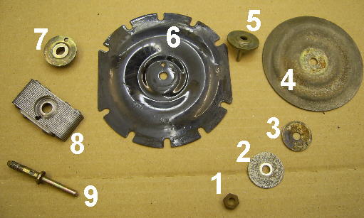
Fig. V.5-2: Individual parts of the membrane unit from the outside (1)
to the inside (9)
When the membrane is in the rest position, the
contact in Fig. V.5-3 (K) is closed and the voltage applied to the horn
connections drives a current through the solenoid. The resulting magnetic field
pulls the iron yoke attached to the membrane inwards, Fig. V.5-2 [8], and at
the same time pushes the contact [K] attached to the Pertinax plate downwards. The
circuit is interrupted, the tensile force becomes zero and the membrane springs
outwards again. The contact (K) closes again and the game starts over. The
vibrations occur so quickly that an audible, loud sound is produced that is
emitted by the membrane like a loudspeaker.
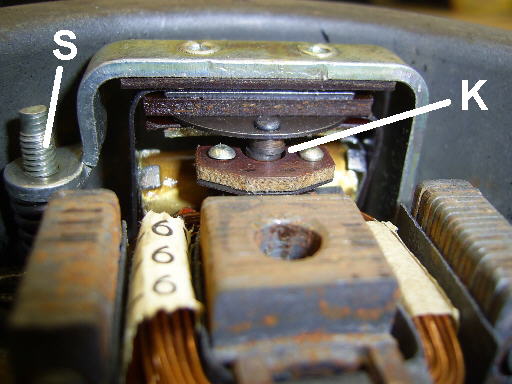
Fig. V.5-3: Contact (K) moved by the membrane and external
adjusting screw (S)
If the horn fails, there is almost always a
contact or adjustment problem, which can usually be easily rectified. To do
this, first remove the decorative panel (if present) and the membrane. The
membrane unit consists of a large number of individual parts (see Fig. V.5-2),
the assembly sequence of which you should definitely record.
The contact (K) must be closed when the membrane
is removed. If it is visibly open, there is a gross adjustment error. The
adjusting screw (S) on the outer underside of the horn must then be turned
clockwise until the contact closes safely (!).
The resistance is
now measured on the cleaned connection terminals with the multimeter. If it is
well above 0.6 Ω (6 V
horn) or 1.2 Ω (12 V
horn), the contact (K) must be cleaned. The resistance values are
empirical, they can vary depending on the model. The contact is pressed down
strongly (the restoring force is relatively large!) And both contact surfaces
are sanded with a strip of hard parchment paper. Only in the case of stubborn
corrosion / erosion may exceptionally help with sandpaper (500 or finer). You
can immediately convince yourself of the success of the action by measuring the
resistance again.
If the contact is opened during the resistance
measurement, the display jumps to "infinite". If this is not the case
- which is extremely rare - there may be a short circuit due to insulation
damage or a defective interference suppression capacitor. In the horn model
shown in Fig. V.5-3, the interference suppression capacitor can be found under
the small Pertinax plate with the contact (K).
If all irregularities have been eliminated up to
this point, the horn - including the
decorative panel with cardboard or Pertinax disc - is fully assembled. The
fastening screws must be tightened so that they are fully tightened; if the
screw connection is loose, neither a clean sound nor a reliable function can be
achieved.
Before voltage is applied, the horn must be
pre-adjusted , otherwise the
setting will turn into a single "blind flight". To do this, proceed
as follows: The multimeter is connected and the resistance value is observed. Depending
on the situation, we proceed according to case 1 or case 2:
Case 1: Display "infinite". The membrane opened the contact when the horn
was screwed together. With the adjusting screw on the base of the horn, the
point is searched clockwise at which the display switches to the low resistance
value. To be on the safe side and keep the resistance low, let's turn it a
quarter turn.
Case 2: Display "low resistance value -
approx. 0.5 Ω ".
The adjusting screw
is brought anti-clockwise to the point where the display jumps to
"infinite". Then the adjusting screw is turned back again until the
low resistance value is displayed, just to be on the safe side we turn a
quarter turn further to keep the low value.
Now it is tested for the last time whether the default
setting is correct (see Fig. V.5-4). In the idle state, the low
resistance value - in the example 0.5 Ω - is displayed. We boldly press the membrane inwards
with our thumbs - the display instantly switches to "infinite".
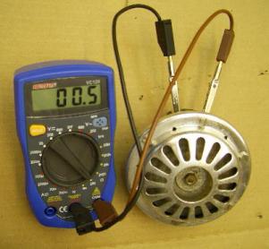
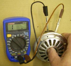
Fig. V.5-4
left: membrane in rest position (0.5Ω), right:
membrane pressed in (resistance infinite)
It is essential
to use a well-charged vehicle battery for the sound setting or the
operational test .
The estimate of the
peak current for the 6 V horn shown above gives
I = 6V / 0.5 Ω = 12 A. It is therefore clear that DC power
supplies that are able to deliver significantly less current are absolutely
unsuitable for commissioning , even if the actual mean operating current
is significantly lower (at 6- V-horns 2 ... 5 A, with 12-V-horns approx. 1
... 2 A). Equally unsuitable are chargers that could perhaps supply the
current, but do not allow the setting of a clean tone because of the usually
unsmoothed, pulsating direct current.
If we connect the voltage, either a continuous
tone sounds or at least a powerful "pop" of the membrane. By
carefully turning the adjusting screw in 1/8 steps, you are looking for the
loudest and cleanest sound. In the end, it will be barely more than one turn
from the pre-adjustment point.
Since the horn's output is quite generous at 15
... 30 W, the horn should not be played for too long while it is being set, in
order not to overheat the inner coil and to protect the neighbors' nerves.
For the described
setting procedure it was assumed that the horn is in its original condition,
i.e. that parts are neither missing nor put together in the wrong order.
Another degree of
freedom when setting the horn is the distance between the iron yoke of the
membrane Fig. V.5-2 (8) and the iron coil core (air gap in the rest
position). Depending on the design of the horn, it can be changed with the
diaphragm pin (9) and the diaphragm nut (1) or by adding spacers. If the
distance is too great, the volume remains low. If the distance is reduced, it
must be ensured that the iron yoke of the membrane can vibrate freely without
touching the inner iron core. After changing the distance, the horn must be
readjusted with the adjusting screw (S).
From the text it is
surely clear that the "intonation" of the horn is not quite as
trivial as it appears at first glance. The most common mistakes are haphazard
"rattling" at the adjusting screw, corroded contacts (outside and
inside), non-optimal air gap and unsuitable voltage sources. Often times I
couldn't help but smile when, after the first inspection of the horns entrusted
to me, it became clear at which point the last test pilot had broken off his
blind flight in frustration ...
V.6
Electronic tachometer (eDZM)
A rotating magnet system (air-core meter) was used as the measuring
mechanism for the speed display. In contrast to the classic cross-coil
measuring mechanism, the coils, offset by 90 °, are arranged as a stator and
the rotatable magnet as a rotor in the inner air space of the coils (see Fig.
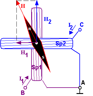
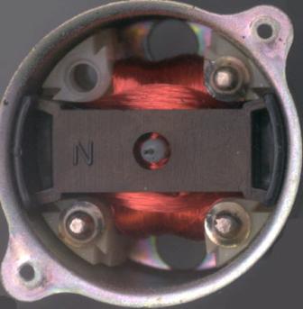
Fig.
V.6-1: Basic and real structure (pointer and scale removed)
a rotary magnet measuring mechanism
The currents I1 and I2 generate the magnetic field components H1 and H2 in the coils 1 and 2 , which are superimposed in the inner air
space to form the resulting magnetic field H.
The rotary magnet rotates like the needle of a compass in the resulting direction
of H and remains in this position.
Remarkably,
·
That this measurement principle works without return
spring gets along (= robust mechanical construction)
·
That if both current polarities are used, a display in
all 4 quadrants, ie up to 360 °, is possible
·
That the display is independent of the absolute
magnitude of the currents. Only the ratio of the two currents determines the
display angle.
It is obvious that the generation of the two coil currents in the correct
ratio to one another from the measured variable (eg from a frequency
proportional to the speed) requires relatively complex signal processing. The LM1819N circuit , which contains all
the necessary components in an integrated form, was therefore used to control
this measuring mechanism .
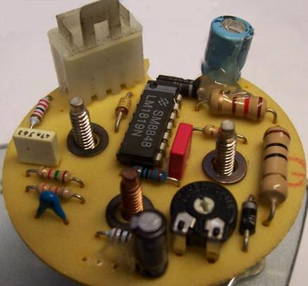
Fig. V.6-2: Tachometer board with control circuit LM1819N
(Photo: MZ Werner
/ mz-forum.com)
The circuit read out from the board (Fig. V.6-4) largely corresponds to
the typical application published in the data sheet for the circuit LM1819N
(National Semiconductors, 1995 edition). D2 serves as reverse polarity
protection and D1 as overvoltage protection. With D3 a reference potential of
about 5V is generated at (A), so that, based on this, negative and positive
voltages are possible at (B) and (C). In front of the internal signal input at
Pin10, a multi-stage low-pass circuit ensures that the signal is formed and at
the same time effectively suppresses interference peaks. This RC combination
can be designed differently, depending on whether the speed signal is taken
from the ignition or the phases of the three-phase LiMa. The elements on pins
5, 6, 8, 9 determine the sensitivity of the deflection of the pointer as a
function of the Measurand. With R5 the
display can therefore be varied within certain limits.
|
N [min -1 ]
|
600 |
1200 |
1800 |
2400 |
3000 |
3600 |
4200 |
4800 |
5400 |
|
Signal frequency [Hz] |
|
|
|
|
|
|
|
|
|
|
Ignition box (ETZ, Rotax) 1 pulse / KWU *) |
10 |
20th |
30th |
40 |
50 |
60 |
70 |
80 |
90 |
|
LiMa phase (ETZ) 4 periods / KWU |
40 |
80 |
120 |
160 |
200 |
240 |
280 |
320 |
360 |
|
LiMa phase (Rotax) 6 periods / KWU |
60 |
120 |
180 |
240 |
300 |
360 |
420 |
480 |
540 |
*) KWU = crankshaft revolution
Table V.6-3: Display value depending on the
signal frequency for various DZM deployment types
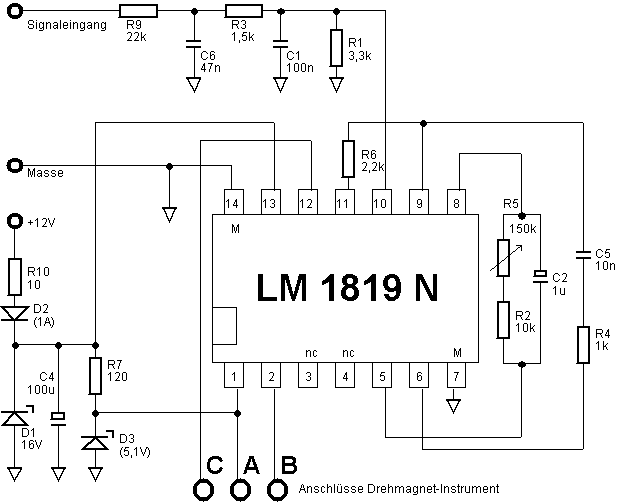
Fig. V.6-4: Circuit read out from the
board (corresponds to the typical application of the LM1819N as a tachometer)
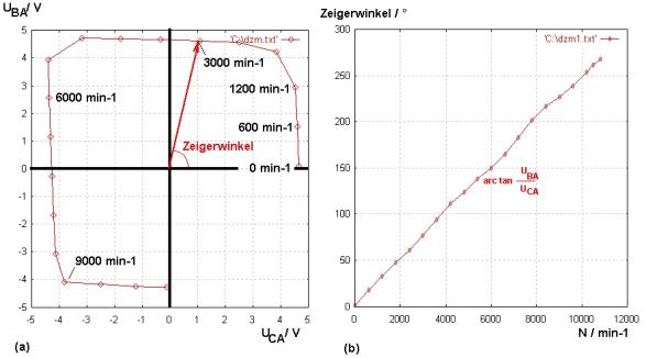
Fig. V.6-5: Measured voltages (a) on the cross-wound bobbins and calculated angle
of rotation (b) depending on the signal frequency (application type: ETZ
LiMa-Phase)
For a DZM (application type: ETZ LiMa-Phase) the voltages across the
cross-wound coils (U CA , U BA ) were measured and shown
in Figure V.6-5 (a). Although the curve deviates significantly from the
circular shape, the back calculation of the resulting angles shows an
astonishingly good display linearity (see Fig. V.6-5).
The relationship between speed display in min -1 and injected
signal frequency in Hz can be removed from the table V.6-3.
(Reference: 3000 min -1 -
200 Hz).
A DC voltage source of around 3 V is required to check the function of
the measuring mechanism. The test is carried out according to Fig. V.6-6. The
connection diagram corresponds to the top view of the threaded pins on the rear
of the measuring mechanism (as in Fig. V.6-2).
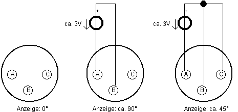
Fig. V.6-6:
Functional test of the rotary magnet
measuring mechanism
The functional test of the circuit board will have to be limited to
checking the operating potentials on the circuit after the operating voltage
has been applied to the +12 V and ground connections: Pin 7 and 14 each zero
volts, pin 13 about +11.4 V, pin 1 about +5 V.
In the complete state, the function of the eDZM can be checked by
applying an AC voltage of ≥20 Vpp to the signal input after connecting
the operating voltage. At 50 Hz, depending on the type of use of the DZM, a
display of 3600 min -1 , 900 min -1 or 600 min -1
will result.
Tests have shown that a square wave form, in contrast to a sinus wave
form, ensures the correct display even for lower signal voltages.
Thanks to
mzkay /mz-forum.com for
providing us with
DZM
devices on which metrological examinations could be carried out.
V.7 The setting of the breaker ignition
The steps for setting the ignition are shown using the example of the MZ
standard alternator 6V / 60W and can be applied to the RT alternator 6V / 30W
or the ETZ three-phase alternator 14V / 15A.
Preliminary remark: If the crankshaft has a perceptible radial
play on the cam or if the crankshaft stub with rotor and cams “wobbles”
perceptibly (> 0.1mm), precise setting of the ignition is impossible or
speed-dependent malfunctions can occur. A new storage or a general overhaul of
the engine is inevitable in such a case!
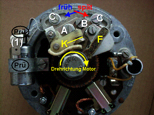
Fig. V.7-1: Alternator 6V / 60W with
breaker ignition
(1) Plug contact for cable to ignition coil terminal (1)
A: Interrupter contact fixing screw
B: eccentric adjusting screw
K: Breaker hammer / contact spacing
C: Break plate fixing screws
Q: Lubricating felt in metal surround
Test: Connection points for test lamp
Preparation: Cams and
interrupter contacts are cleaned and checked for mechanical integrity.
If necessary, the contacts can be processed
with a contact file (very flat file with a special cut) so that when closed
they rest over the entire surface. In the repair instructions it is recommended
to remove the breaker hammer for this work. However, it is more practical to
insert the file between the two contacts and to press them lightly against one
another while filing so that the parallelism of the contact surfaces is
automatically maintained. File chips must be carefully removed after
processing!
If the craters are beyond recovery, the
interrupter must be replaced. The breaker hammer is pushed onto the shaft that
has been wetted with a little breaker oil (eg ADDINOL U 1500) and fixed.
Severe contact erosion in a short period of time can be caused by a
defective ignition capacitor, among other things. With the help of a suitable
digital multimeter, capacity (target:
0.22 µF + 20 / -10%) and insulation resistance (target:> 20 M W ) can be checked.
Setting the contact distance K: Turn the crankshaft with a 14 or 13 ring
spanner (clockwise) (candle unscrewed) so that the cam opens the interrupter
contact the widest at its highest point (cam peak).
The contact must not decrease or even close at
any point on the Nockenberg (“Nockenberg with saddle”). This can possibly be
the cause of an increased tendency to reverse the direction of rotation of the
motor at low speed. In this case, the cam must be replaced by a perfect one
with a constant radius "on the mountain".
Loosen screw A (see Fig. V.7-1) just enough so that the contact
with the eccentric screw B can be moved without using excessive force.
In the case of breaker plates without an eccentric screw, breaker contacts
with so-called notch adjustment are used. A suitable screwdriver is
inserted into a notch and the contact is moved by carefully tapping the
screwdriver handle with a piece of wood.
The setting dimension is usually given as 0.4 mm. The check is carried
out with a corresponding feeler gauge. Distance gauges 0.3 / 0.6 or 0.4 / 0.6
are included in the original vehicle tool kit. If the distance cannot be
adjusted, a worn foot of the breaker
hammer may be the cause. The contact is then unusable and
must be renewed.
As a final check, we turn the crankshaft 360 ° in the direction
of engine rotation (clockwise) and check the distance with the feeler
gauge. The contact spacing often changes again when the fastening screw A is
tightened . The procedure must then be repeated until the specified breaker
distance is met in the fixed state.
Tools for setting the ignition position:
·
Test lamp 12V (might as well be used for 6 V systems)
·
Zündeinstelllehre for determining the piston position OT ( o
berer T otpunkt) and the ignition position before TDC.
In [2] 1st edition p. 205, Fig. 4.33 and 4.34,
simple setting gauges for vertical or
inclined plug holes are shown.
In addition, various MZ repair instructions
refer to special tools such as the ignition setting gauge H8-2104-3 (see Fig.
V.7-2) or H8-1408-3 (see Fig. V.7-3). However, these are sought-after
collector's items and are more intended for showcases than show pieces, because
they are now traded at astronomical prices.
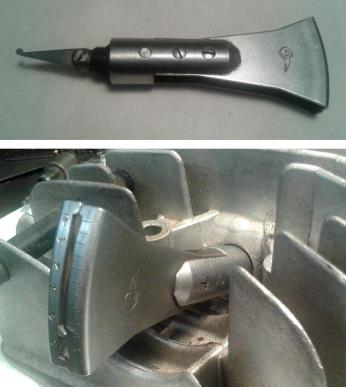
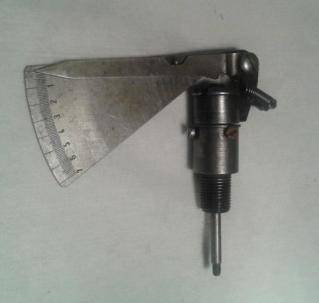
Picture V.7-2: Zündeinstelllehre
H8-2104-3 image
V.7-3:
Zündeinstelllehre H8-1408-3
for oblique candle
hole for
vertical candle hole
(Photos:
Christof, mz-forum.com)
Setting tools with a dial gauge and plug thread adapter
(Fig. V.7-4) for vertical plug holes are more practical and easier to obtain . For
inclined candle holes only the self-made degree disc or comparable
aids remain .
Figure V.7-5 shows a simple
self-made solution. An old socket wrench socket (SW 13 or SW 14) is prepared so
that it can be clamped with two small screws on the hexagon head of the M7
rotor screw. A correspondingly angled pointer (bicycle spoke ) is
attached to this
clamping piece. A paper strip is placed on the housing
of the alternator, which has the markings for TDC and the preignition - in the
illustration for example for 3 ± 0.5mm from TDC. The dimensions for the division can be found in the
tables for the corresponding motor type in Appendix Z.7.
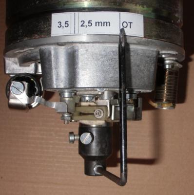
|
Fig. V.7-4: Dial gauge with plug
adapter and feeler pin extension for vertical plug hole |
Fig. V.7-5: Pointer clamped on the
hexagonal head and applied marking strips (example for ES150, target: 3 mm
from OT) |
Setting the ignition position
The ignition position is often referred to colloquially as the ignition
point (ZZP) , although strictly speaking it is not a time parameter.
After the candle has been unscrewed, the components of the existing
ignition setting gauge are mounted.
The two screws C of the breaker plate (Fig. V.7-1) are only
loosened so far that the plate moves when gentle blows are given to the nose
located between the screws (tap on a screwdriver with a piece of wood).
The test lamp is between the capacitor
connection (1) and ground
(see connection points Prü in Fig.
V.7-1).
The ignition is switched on with the ignition light switch, the idle and
charge control lamps light up. However, current also flows through the ignition
coil (3 ... 4 A) when the breaker contact is closed. The adjustment process
should therefore not take too long in order not to overheat the ignition coil
and to save the battery.
Turning the crankshaft searches for top dead center (TDC) . It is
reached when the screwed-in dial indicator shows a maximum or the feeler rod
protrudes the furthest from the plug hole. The breaker contact is now open and
the test lamp lights up.
TDC is the zero or reference
point (= 0 mm before TDC or = 0 ° before TDC) for the ignition timing. The pre-ignition in mm before TDC
or the pre-ignition angle in °
before TDC is always related to it.
(a) Rough presetting:
The crankshaft is turned counter-clockwise until
the required value of the pre-ignition on the dial gauge, feeler gauge, degree
disc or marking strip is reached. The exact values depend on
the engine and must always be taken from the relevant operating instructions
. In terms of magnitude, they are around 3 mm or 22 ° before TDC.
If the interrupter is equipped with a centrifugal
adjustment (before 1970), the centrifugal weights must be pushed completely
outwards during the entire adjustment using a device provided for this purpose.
By moving the interrupter plate in the
"early" or "late" direction (see Fig. V.7-1), the position
can be found in which the test lamp has just reached the switching point by
changing "lights" <-> "not lights" signals. This
switching point corresponds to the position at which the ignition spark is
triggered.
The contact on the Nockenberg is open and the
test lamp lights up,
it is closed in the cam valley and the test lamp
remains dark.
(b) Fine adjustment, correction:
The ignition position is always checked by turning the crankshaft in the
direction of engine rotation (clockwise) past the switching point
while observing the setting gauge and test lamp. Once the breaker plate is
fixed, the setting values must be checked again and corrected if
necessary.
Finally, the contact distance must be checked again. If it has changed
unintentionally when moving the breaker plate (which unfortunately is often the
case), there is no other option than to repeat the entire setting procedure,
whereby the corrections are getting smaller and smaller and you will find a
satisfactory one after several such "cycles" State is approaching.
Various tips and hints for setting the ignition
When assembling the interrupter contact , make sure that the guide
pin Z goes into the intended hole in the interrupter plate (see Fig. V.7-6).
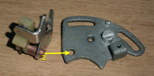
Fig. V.7-6: Guide pin Z
of the breaker contact and breaker plate
The maintenance intervals for the breaker
ignition (contact distance, ignition position) were specified for the RT types
with 2000 km, with the ES types with 2500 km and from TS to ETZ with 5000 km. A
check at the beginning of the season is definitely recommended.
After installing a new breaker contact,
the contact distance must be checked after approx. 500km, since experience
shows that the contact surface (hammer base) of the breaker hammer grinds
quickly on the cam at the beginning.
The lubricating felt F (Fig.
V.7-1) is adjusted so that it only touches the cam at the highest elevation
(cam peak). After setting or checking old grease residue from cams to remove
and 2 ... 3 drops breaker oil (eg ADDINOL U 1500) on the Schmierfilz F
to give.
The felt strip under the breaker hammer prevents breaker oil
thrown off the cam from contaminating the contacts. It has to be there!
Since the contact distance with a fixed breaker
plate becomes smaller during operation due to wear of the breaker hammer
on the cam, the ZZP shifts in the “late” direction.
Contact wear increases the contact distance and shifts the ZZP in
the "early" direction. However, this influence is over-compensated by
the wear and tear of the breaker hammer, ie the ZZP always moves towards
"late" after a long period of operation.
Tip: To
protect the battery and ignition coil, the cable on the capacitor (1) can be
removed and the test lamp connected between the battery positive and the
capacitor contact (1). The ignition remains switched off. The signaling of the
test lamp is now reversed: When the contact is closed (cam valley) it lights
up, when the contact is open (cam hill) it remains dark.
Why pre-ignition?
The pre-ignition basically causes the mixture to
ignite before the top dead center is reached. This should lead to an optimal
course of the combustion pressure after the piston has exceeded TDC. However,
since the time for the pre-ignition with a fixed ignition position becomes
shorter and shorter with increasing speed, the time for the pre-ignition
shrinks to the same extent. With a pre-ignition angle of 22 °, for example, the
pre-ignition time at 1000 min -1 is just under 4 ms, but only 0.6 ms
at 6000 min -1 . The example is intended to make it clear that
excessive precision when setting a fixed pre-ignition position is actually not
justified. With a speed-dependent pre-ignition (ignition curve)this
effect can be more or less counteracted. The MZ two-stroke engines - including
those with centrifugal adjustment - generally have a fixed ignition position at
operating speed.
What is the meaning
of the contact distance?
During opening, the
voltage across the contact increases rapidly and can reach tens to hundreds of
volts until the spark triggered on the candle stops the voltage increase. The
rate of voltage rise is determined by the capacitance of the ignition
capacitor; the smaller the capacitance, the greater the rate of rise.
If the contact
distance is too small, voltage flashovers can occur between the contacts, which
leads to increased wear. The voltage flashover limit in air is around 3000 V / mm, ie when the
contact is fully open (0.4 mm) there is no flashover as long as the voltage
remains below 1200 V. However, if the contact is only opened 1/30 mm during the
movement, the rollover limit at this point in time is only around 100V.
Problem: ZZP cannot be adjusted in the
adjustment range of the base plate
The assignment of piston position and cam
position is subject to tolerances. Responsible for this is the actual position
of the fitting grooves on the crankshaft stub, the LiMa rotor and the cam. The
problem described above can arise particularly when a new cam from
re-production or unknown stocks is installed.
If an assembly error within the LiMa is
definitely ruled out, the rotor can be fitted slightly rotated. To do this, the
key on the crankshaft stub must be removed beforehand. An offset in clockwise
direction causes the ZZP to be shifted to "early" and vice versa.
V.8 Vehicle light bulbs
The test
voltage of an incandescent lamp is understood to be the operating voltage for which
it is designed, ie to which electrical (e.g. power), photometric (e.g.
brightness) and service life specifications refer. The values
were specified in regulation ECE R 37.
|
nominal voltage |
Test voltage according to ECE R37
|
|
|
|
|
6 V |
6.3V |
|
12 V |
13.2 V (13.5 V for auxiliary light lamps) |
|
24 V |
28 V |
There
is a relationship between the actual operating voltage in the vehicle and the
statistically expected service life or brightness, which is shown in Figure
V.8-1. As a rule of thumb, a 5% permanent increase in voltage halves the
service life and 10% consequently quarter it.
Fig. V.8-1: Relationship
between service life, brightness and operating voltage
of vehicle light bulbs (source:
https://de.wikipedia.org/wiki/Gl üh lampe ,
Primary source not
specified)
Since
the usual on-board voltages are 6.8 ... 7.0 V or 13.8 ... 14.0 V, the
incandescent lamps are already operated with around 10% or 5% overvoltage. According
to the diagram above, only a quarter or half
of the statistical lifetimes specified by the manufacturer can be
expected from the outset , since these refer to the test voltages of 6.3 V or
13.2 V.
The filament temperature reaches values
of over 2000 K during operation. As a result, the differences
between the cold and hot resistance of the filament are very large, they differ
by a factor of about 10 (see Fig. V.8-2).
Fig. V.8-2: Current consumption (I), filament resistance (R) and power (P),
measured on a copy of a 6V / 45W headlight lamp.
The inrush current of a high beam filament
measured on an oscillograph is shown in Fig. V.8-3. In order to achieve the
required current yield of the voltage source, a plurality of 6-V nonwoven
batteries are connected in parallel to the power was indirectly as a voltage
drop across a measuring resistor of 1.5 m Ω determined.
In order to achieve the inrush current peak of
over 50 A, the internal structure of the incandescent lamp must be completely
cold before switching on, repeated switching on in quick succession heats the
interior of the incandescent lamp quickly and reduces the inrush current peak
to half or less. Likewise, there are significantly lower current peaks in the
heated thread system if only a switch is made between high and low beam.
The inrush current lasts about one to two tenths
of a second. During this time, the on-board voltage can "buckle",
which can be expressed in a brief misfire.
Fig. V.8-3: Time curve of the inrush
current of a 6V / 45W headlight
Lightbulb
Z Appendix
Z.1 Circuit
of the electronic 6 V regulator MZ ELEKTRONIKUS
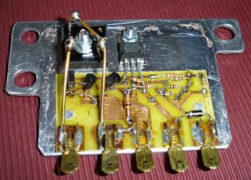
Fig. Z.1-1: Housing and circuit board of the ELEKTRONIKUS
controller
Statement
without guarantee: The metal base plate can be screwed to ground,
as the circuit, diode block and power transistor are arranged in an isolated
manner.
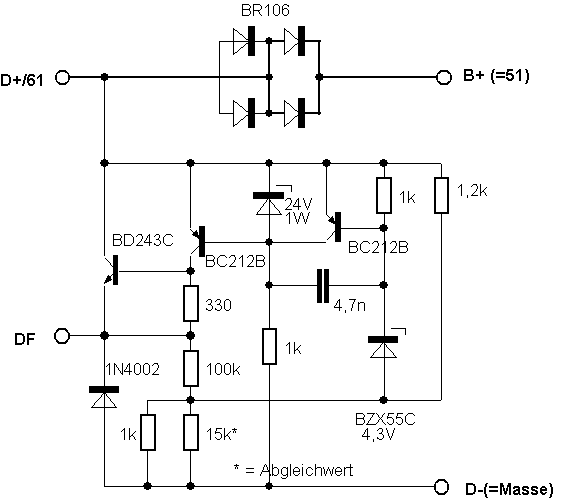
Fig. Z.1-2: Circuit of the ELEKTRONIKUS controller
The circuit of the ELEKTRONIKUS corresponds to the classic solution of
a discrete analog regulator for direct current LiMas.
The BZX55C-Z-diode together with a base-emitter forward voltage (right
BC212B) and the voltage drop over 1k
// 15k * form the voltage reference in the regulator. If the generator voltage
at D + / 61 increases, the right BC212B begins to draw current and at the same
time blocks the left BC212B. As a result, the base potential at the BD243C
drops and the field current at DF is reduced, so that the voltage increase at D
+ / 61 is counteracted.
The 15k * resistor is used as a balancing element with which the
regulator voltage can be varied within small limits. For more coarse voltage
adjustments, the Zener diode must be changed.
The testing of the controller outside the vehicle can be carried out
according to the procedure described in Section A.3.2. The controller can
easily be repaired if necessary, since the components are freely accessible.
Photos and circuit
reconstruction of the ELEKTRONIKUS: TeEs (mz-forum.com)
Z.2 Electronic controller for permanently excited
Rotax-LiMa
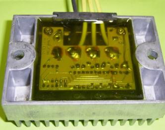
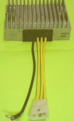
Fig. Z.2-1: Identical funnel / regulator for Rotax-LiMa
The encapsulated rectifier / regulator for the permanently excited
three-phase LiMa of the Rotax motor is located in an aluminum housing with cooling fins .
Thanks to the
crystal-clear potting compound, the conductor tracks on the embedded circuit
board are easy to see. The controller works according to the short circuit
principle. If the output voltage at terminal (30) becomes too high, the two
transistors begin to carry current, so that finally 270 Ω, 100 Ω via the
voltage divider one or more of the
thyristors S4020 switch the respective phase for one or more half-waves in a
row to ground. Part of the unused power is converted into the current-carrying
diodes or thyristors, while the greater part is converted into the generator
windings of the LiMa. The not inconsiderable power loss is the reason why this
type of LiMa / controller can only be used for relatively small outputs
(nominal output here: 190 W) in the moped and motorcycle sector. The
field-regulated three-phase LiMa continues to hold its own for high electrical
power in vehicles.
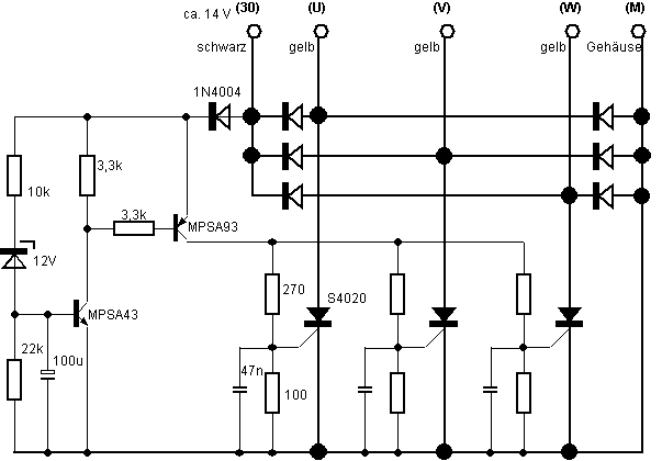
Fig. Z.2-2: Circuit of the rectifier / regulator block for
the Rotax-LiMa
Z.3 P ermanent-excited LiMa with rectifier /
regulator and ignition
Z.3.1
Regulator / rectifier for 2-phase LiMa
Low-maintenance and
high-performance permanently excited alternators are also enjoying increasing
popularity in older motorcycles, as the traditional 6 V direct current or 12 V
three-phase LiMas are being replaced.
The special
regulator circuit shown below (Fig. Z.3-1) is used to rectify and stabilize a
2-phase alternating voltage. The rectification takes place with the help of a
(controllable) bridge circuit, which consists of the diodes or thyristors shown
in bold.
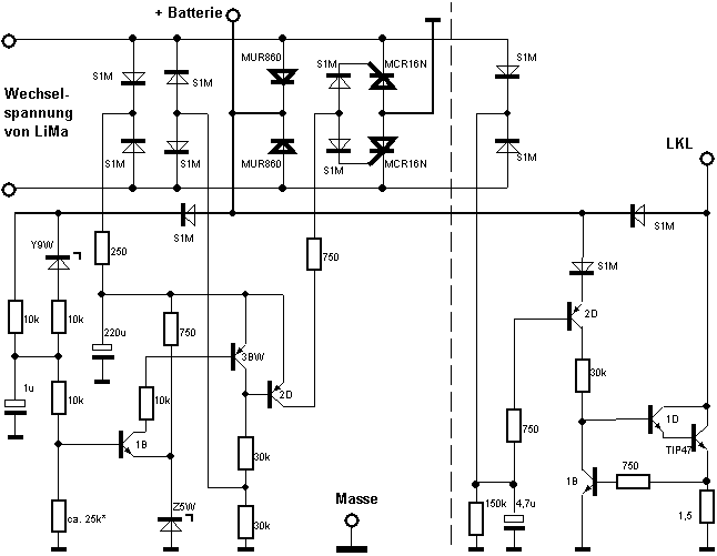
Fig.
Z.3-1: Circuit of the
electronic 12 V regulator for 2-phase permanently excited LiMa
In contrast to the
method widely used in the motorcycle sector of brutally short-circuiting AC or
three-phase windings using thyristor switches in the event of excess voltage,
the rectifier bridge remains ineffective on one side in this circuit in the
same situation, since the thyristors block. However, if they act as diodes when
ignited, the generator winding works via the
rectifier bridge on the DC voltage output, ie on the battery and / or
consumer in the on-board network.
In contrast to the
three-phase LiMa with 3-phase rectifier bridge (see Section B), the resulting
DC voltage after two-way rectification systematically has a relatively large
pulsating component. A connected lead-acid battery or an optional capacitor
should ensure sufficient smoothing of the on-board voltage outside the
controller so that sensitive consumers are not impaired in their function.
The internal voltage
standard (reference) is formed in a conventional manner by the lower 6.8V Zener
diode Z5W in cooperation with the base-emitter path of the npn transistor 1B. A
temperature-stable reference can therefore be assumed. Elements that indicate
an adjustment of the battery charging voltage at different temperatures (see
Fig. V.2-3) are obviously not present.
The following
oscillograms (Fig. Z.3-2), which were recorded on a complete system LiMa /
controller / ignition in a TS250 / 1, show the voltage curves at the controller
output with different loads.
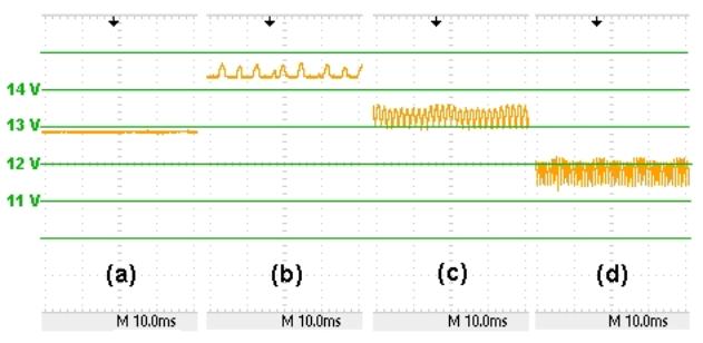
Fig. Z.3-2: Voltage curves at the controller
output with different load cases
(a) When the motor is at a standstill, the battery
(fleece, 12 V / 11 Ah) can be read off at an open circuit voltage of around
12.8 V.
(b) Without load (2000 min -1 ), the
on-board voltage climbs to 14.4 V, with pulses of up to 0.5 V peak being
applied to this in a random sequence. It can be clearly seen that due to
insufficient power consumption, only every 2nd or 3rd rectified half-wave is
switched through to the vehicle electrical system.
(c) With a load of 4x21 W and a speed of 3000 min -1
, the voltage drops to 13.0 V with a pulse component of 0.6 V peak. On average,
this corresponds to about 13.4 V. Every half-wave is continuously switched
through into the on-board network, there is nothing more to regulate.
(d) With a further increase in load to 8x21 W, the
on-board voltage consequently drops further, as expected - despite the increased
speed (approx. 5000 min -1 ) - to 11.4 V with a pulse component of
0.6 V peak.
The part to the
right of the dashed line in the circuit is used to control the charge control. As
long as the generated voltage is below the battery voltage, the pnp transistor
2D sends a current - multiplied by the npn transistor 1D - to the power
transistor TIP47, ie the LKL lights up. The voltage feedback to transistor 1B
ensures that the current at the LKL output remains limited to a few 100mA.
If a battery is used
together with this type of controller, a small amount of current always flows
into the controller, even when the engine is not running. The causes are
distances through internal resistances and residual currents from pn junctions.
Practically 0.8mA was measured on one example at 12V. That sucks a lot of 1 Ah
from the battery in a 2-month winter break. This discharge is by no means
critical, but you should be aware of the fact, especially when batteries with
small numbers of ampere hours are used for backup.
Testing the controller
The possibilities of
testing the controller outside the vehicle are very limited. If anything, they
should only be done by experienced people who are aware of what exactly they
are doing at each test step.
The function of the two rectifier diodes
CQ735 can be checked between an AC voltage input and the + battery output
(analogous to the measuring circuit in Figure B.2-2 in reverse and forward
direction).
The mentioned quiescent current consumption can be measured
if a 12 V battery is connected between + battery and ground. Although this is
normal operation when using batteries, a 12V / 21W light bulb should be looped
in beforehand to limit the current. A reading around 1 mA or below will be
okay.
The function of the charge control can be
checked externally. Both AC voltage inputs are connected to one another
(corresponds to the situation when the motor is at a standstill). A control
lamp connected to LKL against + 12V must light up. If the connection of the AC
voltage inputs is disconnected and any of the two are connected to the +
battery input, the LKL will go out.
An external check of
the stabilization function of the
controller is possible, but does not make much sense because a controllable AC
voltage source with a LiMa-comparable output is required. It is easier to
connect the controller to the safely functioning alternating voltage generator
(prior check with aOperate the
headlight lamp as a substitute load in the vehicle as in Figure B.1-3) and measure
the terminal voltage on the battery or consumer. With this measurement,
however, incorrect displays can easily occur, since it is a direct voltage with
a more or less pulsating component and this signal form is often not displayed
as a correct mean value, especially by simple digital multimeters. The safest
way - as anachronistic as it may sound - is to use a conventional moving-coil
pointer instrument for this special measurement. To improve its display
accuracy, it should be calibrated beforehand on a 12V battery in comparison
with a digital multimeter display.
Z.3.2
Electronic ignition (CDI, similar to vape)
With conventional break contact ignition, the
very high ignition voltage arises from the sudden interruption of the primary
ignition coil current through the break contact.
With the so-called
CDI ( C ondensor D ischarge I gnition = capacitor discharge ignition), on the other hand, a
capacitor charged to several 100 V is suddenly connected to the primary side of
the ignition transformer using an electronic switch (see Fig. Z.3-3). This
transforms the voltage jump to a few kV, so that finally a spark jumps over the
candle. The CDI has a very good efficiency, since an unnecessarily long flowing
primary direct current (a few A for each 180 ° KW rotation) is not necessary as
with the breaker contact ignition. The voltage of the generator winding of the
LiMa in the is sufficient to generate the capacitor charge voltageAs a rule, this is not the case, so
a separate charging coil (L) is provided for it. This also has the advantage
that the ignition can work independently of the generator and battery.
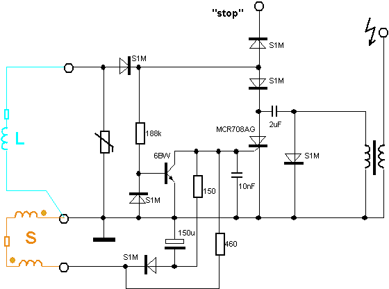
Fig. Z.3-3: Circuit of the electronic CDI (charging coil
(L) and sensor coils (S) are located on the stator of the LiMa)
In the oscillogram shown below (Fig. Z.3-4) the
turquoise curve shows the charging coil voltage. At around 1500 min -1
it already reaches peak values of over 500V. The north and south
poles on the inside of the rotor, each offset by 30 °, produce 6 complete
periods of the charging voltage per KW rotation (this also applies to the
generator winding of the LiMa).
The two sensor coils are offset from one another by 30
° so that there is a magnetic south pole above one when the other is being
swept by a north pole or vice versa. This leads to opposing voltages which
(practically almost) cancel each other out in the series connection of the two
coils. In the inner circle of the rotor, however, a 30 ° segment is not
equipped with a permanent magnet. If the sensor coils cover this “gap”, the
compensation in the first coil and then in the second is missing. The result is
that there is a positive impulse, followed by further ones, until the “rotor
anomaly” has moved on. The first, large positive impulse triggers the thyristor
MCR708AG, which - suddenly turned on - causesthat the charge of the 2 uF
capacitor is "poured" into the primary side of the ignition
transformer (points in time marked red in the oscillogram).
The following positive charging coil wave safely
switches the thyristor off again via transistor 6BW so that the game can start
again.
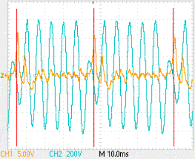
Fig. Z.3-4: Voltage-time curve at
the sensor (orange) and charging coil connection (turquoise). Deflection
orange: 5V / part, turquoise: 200V / part and time: 10ms / part. Red :: marking
of the ignition timing
Special testing of the CDI module outside of
the vehicle is not recommended because of the complex test environment
required.
Special thanks go to all Foristi who contributed
to the creation of the descriptions in section Z.3. have contributed in a
practical and / or theoretical way!
Z.3.3
Rotax: Electronic ignition (CDI, Nippondenso)
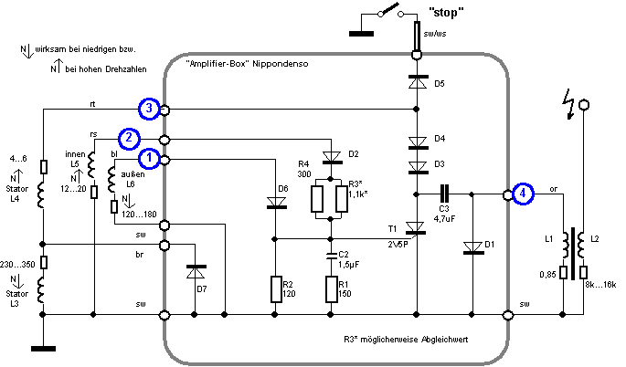
Fig. Z.3-5: Internal circuit and connection of the
Nippondenso ignition box (amplifier box).
Circuit reconstruction: dösbaddel
(mz-forum.com)
Measuring points (MP):
(1): outdoor sensor, (2): indoor sensor, (3):
charging voltage, (4): CDI pulse
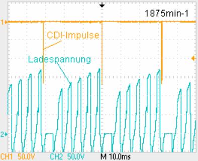
Fig. Z.3-6: Charge voltage
curve (MP 3) and CDI pulse (MP 4)
A charging voltage is generated in the stator
coils L3, L4, the positive half-waves of which charge the capacitor C3 to
approximately +170 V via D4, D3 (see Fig. Z.3-6).
In order to generate a sufficiently high
charging voltage even at low speeds, L3 is selected to be correspondingly
large. However, with increasing speed or frequency, their alternating current
resistance increases steadily, which prevents C3 from charging quickly. L4
therefore takes over charge at higher speeds.
If the thyristor T1 is switched on, C3 discharges
in a fraction of a millisecond and generates a narrow CDI pulse of around -170 V on the primary winding of the
ignition coil, which transforms the ignition voltage pulse accordingly on the
secondary side.
The switching point of the thyristor is
controlled by two transmitter coils. The external encoder coil is arranged 3 °
before TDC. It generates a steep positive edge per KW revolution, which
switches on the thyristor at around 1.8 V (see Fig. Z.3-7). With increasing
speed, however, the flatly rising voltage of the internal encoder increases so
that it reaches the switching threshold of the thyristor earlier, which pushes
the ignition point forward.
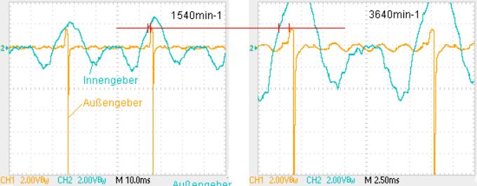
Fig. Z.3-7: Encoder voltages (MP1, MP2) at lower and
higher speeds.
If the CDI ignition pulse is
selected as the time reference, you can see in Fig. Z.3-8 how the external
encoder pulse moves away from the ignition pulse with increasing speed.
At 3530min-1 the CDI
ignition pulse comes roughly before the external sensor , ie a total of 24 °
before TDC. ![]()
R3 * in the amplifier box
could be provided as an adjustment element to influence the takeover point of
the external and internal encoder
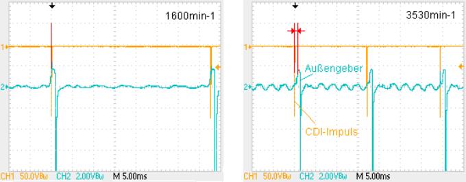
Fig. Z.3-8: Speed- dependent
shift of the CDI ignition pulse compared to the
Control pulse from the external encoder
When the “stop” switch is
pressed, the charging voltage input (MP 3) is connected to ground via diode D5.
The capacitor can no longer be charged and the ignition spark disappears
immediately.
Z.4 12V regulator circuit L
9480 in the ETZ
Z.4.1 Properties of the L9480 control circuit
At the beginning of the 1990s, the L 9480 regulator circuit from
SGS-THOMSON Microelectronics was used in the last 2-stroke MZs with the 14V /
15A three-phase alternator.
The L 9480 works digitally as a switching regulator. Its functionality
can be compared to that of an electromechanical controller, although the work
of the mechanical controller contact is of course taken over by an electronic
switch.
Lt. Data sheet the controller is very robust, it has a thermal overload
protection, withstands battery polarity reversal, short circuit and overvoltage
(up to 80V).
The nominal control voltage specified is 14.4V ± 1% at 25 ° C. Elsewhere
in the data sheet, however, there is a spread of 14.1V to 14.7V, which
corresponds to about ± 2%.
The control voltage has a temperature coefficient of -10mV / K. This
accommodates the temperature behavior
of 12V lead-acid batteries, although -24mV / K would also be required for full
compensation .
The application of the circuit in the TO220 housing with three
connections shown in Figure Z.4-1 is very simple.
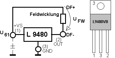
Fig. Z.4-1: Application of the L 9480 control circuit
The wiring according to Fig. Z.4-1 shows that this - in contrast to the
original electromechanical controller in the 12V-MZ - is a minus-regulating application . Connection (1) is connected to
terminal (61) (= LiMa voltage after the auxiliary rectifier), connection (2)
goes to the field winding connection DF-. The metal lug of the housing and
connection (3) are ground, ie the circuit can be screwed onto the vehicle frame
without electrical insulation.
Although the controller has internal filters, a capacitor of 0.1 ... 1µF
from (1) to (3) is recommended on the input side in order to limit interference
peaks. This capacitor would then also be the only additional element for the
application.
Z.4.2 Measurements on the L9480 circuit
The voltage U FW across the field winding (Fig. Z.4-1) is
decisive for the excitation current through the field winding , more precisely,
its mean value, since it is a pulse-shaped voltage-time curve. In the
following, the addition “avg” stands for the formation of the time average: avgU FW = U 61 - avgU
OUT .
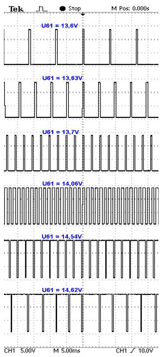
Fig. Z.4-2: Switching voltage at (2) OUT of the L 9480 controller
Since U 61 fluctuates only slightly around 14V in regulated
operation, it can be assumed that as the mean value of the voltage at the
circuit output avgU OUT increases , the above difference decreases,
i.e. avgU FW decreases, which means that the excitation current of
the LiMa is reduced. The oscillograms recorded on a specimen L9480 in Fig.
Z.4-2 illustrate this. For the sake of simplicity, a 12V / 4W light bulb was
used as a replacement for the field winding.
If the input voltage U 61 <13.6V is low, DF- is pulled
against ground (there is a residual voltage of about 1.75V), ie the maximum
possible excitation current flows.
If U 61 rises above 13.6V, the controller output begins to
switch. Since the narrow pulses are still relatively far apart, the mean value
is only slightly above zero. However, the larger U 61 becomes, the
closer the pulses come together and at 14.06V the pulse and pulse pause are the
same size, ie the time average is half of U 61 , i.e. about 7V.
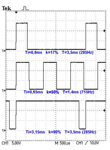
Fig. Z.4-3: The switching pulses for different duty cycles
If U 61 continues to rise, the now negative needles move away
from each other and the mean value continues to rise until it finally reaches
the maximum value, namely U61. Then there are zero V across the field winding,
ie the excitation is also zero.
The oscillograms in Fig. Z.4-3 show
the switching pulses at different input voltages, but with a more finely
resolved resolution.
The positive needles have a constant width of about 0.6 ... 0.65 ms,
while the negative needles are leveled to about 0.35 ms even with larger duty
cycles. The highest switching frequency was achieved with a duty cycle k = 50%
with 715Hz
Figure Z.4-4 shows the mean value of the voltage across the field
winding over time (green curve). This mean value over time determines the
excitation current through the field winding. As expected, the curve drops with
increasing generator voltage (61). In order to regulate the field current from
the maximum value to zero, a generator voltage change at (61) of more than 1V
is required. This low control steepness is the cause of a noticeable
flexibility in the on-board voltage when the electrical load changes.
Fig. Z.4-4: Measured mean voltage avgU FW across the field winding
(green)
and period T of the
pulse train as a function of the
Input voltage U 61
Z.4.3 Installation in the vehicle electrical
system and behavior
The L9480 regulator circuit was added to the on-board network of an
ETZ150. The conversion is shown in Fig. Z.4-5.
Fig.
Z.4-5: Conversion from electromechanical plus regulator to minus
regulating circuit L9480 at ETZ. (a) Original circuit , (b) integr.electron.
Switching regulator
The measured voltage values (see Table Z.4-6) with the
built-in regulator circuit directly at the terminals of the rectifier plate
(61) and (D +) are relatively high. You confirm the values from
the data sheet. At 10 ° C, 14.0V would be the optimal charging voltage for a
lead-acid battery, so the value is at least 0.4V higher during normal driving.
|
Ambient temp. 10 ° C |
2000min-1 |
4000min-1 |
|
without light |
(61) 14.67V (D +) 14.52V |
(61) 14.80V (D +) 14.63V |
|
with light |
(61) 14.53V (D +) 14.32V |
(61) 14.64V (D +) 14.38V |
Table Z.4-6: Voltage values depending on load and speed for
L9480
The two oscillograms shown in Fig. Z.4-7 and recorded in the vehicle
electrical system for the same engine speed, but with different load
conditions, once again illustrate the function of the integrated switching
regulator L9480: The switching frequency remains approximately the same at
400Hz. Without light, however, the positive impulses are broad, with light they
are narrower. The mean value over time is therefore lower under load, ie the
mean voltage across the field coil and thus also the current through the field
coil are greater. This corresponds to the expected behavior, since the
generator needs a higher excitation at
a constant speed but a higher load .
The upper oscillogram in Fig. Z.4-8 (alternating component) shows which
effects the switching pulses have on the voltage in the vehicle electrical
system. The steep switching edges are obviously transferred from the primary
circuit (rotor) to the secondary circuit (stator), just like with a
transformer. Both positive and negative needles with a pulse height of up to at
least 2V can be seen. This certainly does not have a negative effect on vehicle
lighting, it could become critical for electronic components (electronic
ignition, navigation system, etc.), and considerable emissions are to be
expected.
Fig. Z.4-7: Switching pulses at DF- with different load conditions
For comparison, the on-board voltage (alternating component) is shown in
the lower oscillogram in Fig. Z.4-8 when using a standard electronic analog
controller. The course is much smoother, the fluctuations of +/- 0.5V are not
control oscillations, they are speed-dependent with regard to the time course
and are apparently caused by magnetic field inhomogeneities of the LiMa or by
differences in the individual three-phase windings.
Fig. Z.4-8: AC component of the 12 V on-board voltage for L9480 (above) and electronic
ones
Analog controller
(below)
Summary
The L9480 circuit is an inexpensive alternative to the standard
electronic analog regulators for 12V in terms of both size and cost. This is
offset by its decreasing availability, as the IC is no longer in the production
program.
The high nominal voltage and the contamination of the on-board network
with powerful jamming needles should be noted as disadvantageous. The voltage
should be reduced by approx. 0.5V ... 0.8V by an additional diode in the line
from D + to 51, especially when using dense batteries (gel, fleece), with a
diode power loss of 5 ... 8W is to count.
Z.5 battery chargers and their properties
The
following text is about making the connection between the charging regime
(current, voltage, time) and the properties of the charger and accumulator
understandable.
When does
a battery have to be charged at all?
If the
vehicle electrics and battery are intact, recharging is only necessary in
exceptional cases, namely
- if the battery
has noticeably lost its charge due to self-discharge
over a long period of time. In the case of liquid lead-acid batteries,
at 20 ° C, approx. 8% self-discharge per month is expected, in the case of
fleece or gel batteries, 3%.
- if energy was
withdrawn without sufficient recharging.
If the
two situations mentioned cannot explain the loss of charge, the battery is very
likely to be worn out.
Characteristics
of the battery
The
electrical properties of a battery are (idealized) described by 2 parameters
(see Fig. Z.5-1):
- the open circuit
voltage U B , which can be measured as voltage U at
the external terminals of the battery if only the voltage measuring device
is connected and no other consumers. The leeward tension is sometimes also
referred to as "internal tension".
- the internal
resistance R B , which is responsible for a drop in
the terminal voltage U when a load is connected.
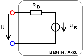
Figure
Z.5-1: Electrical model
of a rechargeable battery or a battery (term: technical voltage source)
If the battery and
measuring device are at hand, both parameters can be determined by exercise. The
measurement specification for U B
has already been given in point 1 (see above).
The internal resistance
R B can only be measured
indirectly. To do this, a consumer must be connected to the battery
(incandescent lamp), which draws about 1/5 of the ampere-hours (equivalent to
0.2C).
Example:
Battery 6 V / 4.5 Ah -> 4.5 [Ah] / 5 = 0.9 [A].
Required power
of the incandescent lamp: 0.9 A * 6 V = 5.4 W.
Selection
of a suitable incandescent lamp with approximate data: 6 V / 5 W
The light bulb is
connected and the battery voltage is observed. Initially, it may decrease
slowly. If it reaches a stable value,
we measure the lamp current (I L ). and the tension. Then we disconnect the lamp. The battery
voltage jumps up by a small amount. We record this difference (ΔU).
The internal
resistance is now calculated ![]()
The open
circuit voltage is 5.6 ... 6.5 V (or 11.2 ... 13.0 V) depending on the state of
charge and the degree of aging. The internal resistance R B is very
low and is a few tens of mΩ in
motorcycle batteries. For the 6 V / 4.5 Ah fleece battery CP645, for example,
22 mΩ is
specified in the data sheet.
Characteristics
of the charger
The
constant voltage charger , like the battery, can be described as a technical
voltage source with open circuit voltage U L and internal
resistance R L (see Fig. Z.5-2). The parameters are
measured in the same way as with the battery. An incandescent lamp can again be
used as a test load, which causes an easily measurable voltage drop at the
terminals of the charger.
This simple electrical model does not apply to
chargers that change their parameters during the charging process by
"observing" the temporal progression of the electrical variables at
their terminals or to devices that do not supply a smooth ("pure") DC
voltage, but one with pulsating components.
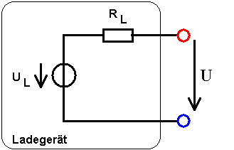
Fig.
Z.5-2: Electrical model
of a conventional DC voltage charger
For the charging process, the charger is connected
to the battery, namely plus with plus and minus with minus.
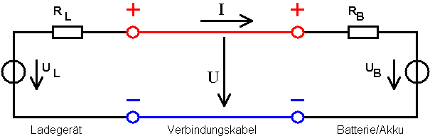
Fig.
Z.5-3: Battery charging
with a DC voltage charger
This
creates the simplest electrical circuit that electrical engineering has to
offer. Our 4 parameters and current I and voltage U on the charging cable are
linked by the following equations:
![]()
If all
parameters of the charger and battery are known, current and voltage can be easily calculated using the above
equation . The results are:
|
|
The
formula shows the well-known fact that U L > U B must
always be in order for a positive charging current I to flow in the
specified direction. Or in the example: A 12 V battery cannot be charged with a
6 V charger.
Example calculation
for charging current
The 6-V
charger have an open circuit voltage of 7.0 V , the battery was pretty
down, he has only 5.9 V . Its internal resistance is 0.05 Ω and the
internal resistance of the charger was determined to be 0.2 Ω .
.
If the
battery is connected, flow according to the formula
![]()
It is now
completely irrelevant whether the charger can deliver 15A or 60A maximum before
its fuse arrives or whatever values are printed on the front
panel. The charging current is simply determined by the voltage difference in
the numerator and the sum of the resistances in the circle in the denominator
of the formula.
If the
internal voltage of the battery has reached 6.9 V after a certain
charging time , only:
![]()
We note
that the charging current decreases to the same extent due to the internal
battery voltage, which increases slowly with the state of charge. If the
internal battery voltage could even reach 7 V, the charging current would be
practically zero and the charging would come to a standstill. However, it would
take a very, very long time to do this because the changes take place more and
more slowly the closer we get to this goal.
Constant
charging with optimal voltage
If the
open-circuit voltage of the charger matches the charge voltage of the battery
(which is optimal for the respective temperature), overcharging can obviously
never occur because the charging process - as shown in the example above - ends
up practically "drying up"
by itself.
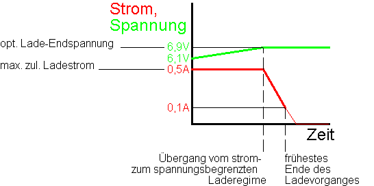
Figure
Z.5-4 Time curve for voltage and current-limited
charging for the example under consideration
This
gentle and harmless charging operation can be carried out very well with an
adjustable DC power supply (e.g. Peaktech 6080 or similar devices). To do this,
first set the optimum final charge voltage of the battery on the supply device
(see Fig. V.2-3).
Then - if
the device has the current limiting function - the maximum permissible charging
current by short-circuiting the voltage output sockets of the device with a
cable for the duration of the setting. If nothing is specified, a tenth of the
ampere-hour number applies as a guideline (equivalent to 0.1C), i.e. 0.5 A for
a 5 Ah battery.
The
supply device is "programmed" in this way and connected to the
battery. The supply device with current limiting function automatically lowers
the charging voltage at the beginning so that the set current limit is not
exceeded. If the charging voltage finally climbs to the target value, the
charging current begins to decrease (see Fig. Z.5-4). The charging process can
be ended when the charging current has dropped to about 1/50 (equivalent to
0.02C) of the number of ampere-hours of the battery.
Continuing
the charging process indefinitely would not lead to overcharging.
Constant
charging with overvoltage (fast charging)
In order
to shorten the charging time, the internal voltage U L of simple
chargers is chosen to be higher than
the optimal final charging voltage of the battery. A larger charging current
flows from the start, charging takes place more quickly, but after a while the
charging voltage exceeds the optimal value and the charging current no longer
goes back to zero. If the charging process is not interrupted either
automatically or manually when the end of charging is reached, the battery will
be seriously and permanently damaged because the gassing limit is exceeded.
Fig.
Z.5-5 Time course for
fast charging
In this
charging mode, it is essential to
monitor the battery voltage and to stop the charging process when the
optimum end-of-charge voltage is reached. The "motorcycle" /
"car" operating modes that can sometimes be selected on simple
chargers are an indication that these are fast chargers whose open circuit
voltage for car batteries has been increased again in order to achieve an even
higher initial current for batteries with a large capacity. If these devices do
not have an automatic switch-off, the charging process must be monitored with a
voltmeter and terminated manually in good time.
Trickle
charge
As the
name suggests, the aim is to counteract the self-discharge of batteries over
longer periods of time. Assuming a maximum of 10% self-discharge per month,
this corresponds to a continuous discharge current of 0.1C / (24h * 30d) =
0.00014C or, in other words, 0.14 mA per 1 Ah battery capacity. With typical
motorcycle battery capacities of 5 ... 15 Ah, these are equivalent discharge
currents of 0.7 mA ... 2.1 mA.
A higher
value can be selected to reliably compensate for self-discharge even with poor
charging efficiency. Normally, the safe continuous charging current is I
<0.01C, i.e. a maximum of 50 mA for the 5Ah battery and 150 mA for the 15Ah
battery.
A trickle
charger with U L = 50 V and R L = 3.6 kΩ would do this well.
We check the trickle charge currents
for a 6V
battery ![]()
and a 12V battery ![]()
This
trickle charger is therefore suitable for both battery voltages, regardless of the battery voltage, it
feeds a harmless charging current of
around 10 ... 12 mA into the battery and thus reliably compensates for
self-discharge. This means that trickle chargers can remain connected to the
battery indefinitely.
Chargers
with pulsating DC voltage
These are very simple
devices, but not entirely unproblematic with regard to the charging regime. Usually
they only contain the mains transformer and one or more rectifier diodes for
one or two-way rectification of the down-transformed mains AC voltage. A
historical representative is, for example, the "Ladefix" (TYPE
GL-3-E12-6 / 6.3Bu), which can still be found often, and can be switched for 6V
and 12V batteries.
Voltage and current curves are shown
qualitatively in Figure Z.5-6. A peak voltage of = 10.4 V was measured on the
device in the 6V regime. When connecting the battery to be charged, a current
flow only occurs if the voltage of the device exceeds the battery voltage. The
original peak voltage is reduced by the current load compared to the no-load
case (Fig. Z.5-6 (b)). Overcharging is possible in principle, since there is
still a current flow when the battery has reached its end-of-charge voltage.
Fig.
Z.5-6 (a) Voltage curve
without connected battery, (b) Voltage and current curve with connected battery
The end of charging must therefore be checked
by measuring the battery voltage. However, since simple multimeters often give
false readings for DC voltage with a pulsating component, it is better to
briefly disconnect the battery from the charger for the measurement. When the
optimum end-of-charge voltage is reached, the charging process is ended,
otherwise it is continued. It is not recommended to leave such a charger
connected to the battery for a long time, because it is not certain that the
average charging current will decrease to a harmless value after charging has
ended. The fixed charging times given in the operating instructions must be
taken with extreme caution, as the current charge status of the battery is
completely disregarded.
Chargers
with 2-point control
A representative of
this type is, for example, the UNILADER VOLTCRAFT TYPE 18410, which among other
things allows 6- and 12V charging. The charging current can be set continuously
between 20 mA and 1.4 A. Usually 0.1C, i.e. a tenth of the ampere-hour number,
is set, ie the device is designed for batteries with capacities between 0.2 Ah
and 14 Ah. Batteries with a capacity> 14 Ah can of course also be charged,
but a longer charging time is to be expected. In Fig. Z.5-7 the function is
shown based on the time curves. With the preset current, the battery is quickly
charged up to the end-of-charge voltage U o , after which the
charging current is switched off electronically. Only when the terminal voltage
on the battery automatically down to a lower voltage limit U u has
dropped, the charging current is back
Fig.
Z.5-7 (a) Voltage curve
without connected battery, (b) Voltage and current curve with connected battery
switched on . The following measurements
were made on the device examined:
U o = 6.98 V, U u
= 6.35 V or U o = 13.94 V, U u
= 12.93 V
Since the upper switching points are safely
below the gassing limit at room temperature, this device can remain on the
battery for as long as required without fear of any harmful effects.
Z.6 Electronic flasher unit 12V (FER GmbH)
The
flasher unit (Fig. Z.6-1) from Fahrzeugelektrik Ruhla GmbH (FER) used by MZ in
the nineties is based on the Temic / Telefunken U243B circuit that was
specially produced for turn signals.
Fig. Z.6-1 Board of the FER flasher unit
The
circuit (Fig. Z.6-2) is specified as a standard application in the data sheet
for the U243B circuit and is used slightly modified.
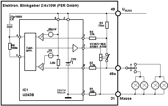
Fig. Z.6-2 Circuit of the FER flasher unit 2 /
4x10W
The combination C0, R0 determines the flashing
frequency. An increase in resistance R0 by x percent leads to a reduction in
the flashing frequency by approximately the same percentage value and vice
versa.
The lamp failure is detected with the help of
the voltage value across the resistor R3. If one of the two indicator lamps
(front or rear) fails, the lamp current - and with it the voltage drop across
R3 - inevitably drops to 50% of the nominal value. R3 is now dimensioned in
such a way that the clock generator generates twice the flashing frequency at a
value of less than 75% of the nominal lamp current. Since the turn signal
control lamp then also flashes at twice the frequency, the driver receives information about the error status. This
signaling function is only guaranteed if incandescent lamps with the prescribed
power of 2x10W per side are used. Resistor R3 would have to be dimensioned
differently for changed lamp power. The signaling threshold is specified
internally in the circuit with 80mV.
The flasher does not work if the connection is
reversed (31 <-> 49), but remains intact. Likewise, a short circuit from
49a to 31 (ground) does not lead to the destruction of the sender, so that - as
is usual with thermo-electric flasher units
Extra protection of the flashing circle is not
necessary.
The circuit board with components assembled in
a standing position will hardly be too resistant to strong vehicle vibrations
(e.g. MZ500R or similar). A subsequent fixation of the resistors and the
electrolytic capacitor with non-conductive two-component adhesive is therefore
recommended.
Z.7 Ignition
position: conversion from (° before TDC) to (mm before TDC)
If the piston stroke H and connecting rod
length L are known, the values of the angle can be calculated
in
Convert
° before TDC and the ignition position in mm before TDC .
In the formulas below mean
H : piston stroke in mm
(crankshaft radius R = H / 2)
L : connecting rod length in mm
(= center point distance lower - upper connecting rod eye)
a : ignition angle in °
X :
ignition position before TDC in mm
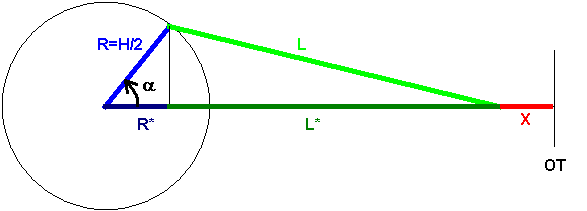
Convert ignition position X [mm] to ignition
angle a [°]:
(X is to be used as
a positive value!)
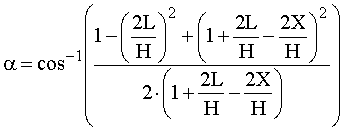
Convert ignition angle a [°] to ignition position X [mm]:
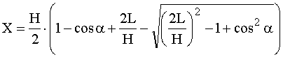
For the MZ types,
the relationship between pre-ignition position and ignition angle is shown in
the following tables. The third column with the name
"Distance on LiMa housing (D =
105mm) from OT" indicates the division dimensions for the paper strip
according to Fig. V.7-5, based on an alternator outer diameter of D = 105mm ..
|
|
Stroke 58mm connecting rod length 125 mm IFA RT 125, RT 125/1, MZ 125/2, MZ 125/3 MM
125/1 (ES 125), MM 150 (ES 150) MM
125/2 (ES 125/1, TS 125, ETS 125) MM
150/2 (ES 150/1, TS 150, ETS 150) MM 125/3 (TS 125), MM 150/3 (TS 150) EM
125 (ETZ 125), EM 150.1, EM 150.2 (ETZ 150)
|
||
|
|
ZZP
in mm
v.OT
|
ZZP
in °
v.OT
|
Distance on LiMa
housing (D = 105mm) mm from OT |
|
|
|
|
|
|
|
2.5 |
21.6 |
19.8 |
|
|
2.75 |
22.7 |
20.8 |
|
|
3 |
23.7 |
21.8 |
|
|
3.25 |
24.7 |
22.7 |
|
|
3.5 |
25.7 |
23.5 |
|
|
3.75 |
26.6 |
24.4 |
|
|
4th |
27.6 |
25.2 |
|
|
4.25 |
28.4 |
26.0 |
|
|
4.5 |
29.2 |
26.8 |
|
|
Stroke 65mm connecting rod length 130 mm BK350,
MM 175 (ES175), MM 250 (ES250) MM
175/1 (ES175 / 1), MM 250/1 (ES250 / 1) MM
175/2 (ES 175/2), MM
250/2 (ES 250/2, ETS 250) MM 250/3 (TS250), MM 250/4 (TS250 / 1) EM 250 (ETZ250), EM 251 (ETZ251), EM 301 (ETZ301)
|
||
|
|
ZZP in mm
v.OT
|
ZZP
in °
v.OT
|
Distance on LiMa
housing (D = 105mm) mm from OT |
|
|
|
|
|
|
|
2.5 |
20.3 |
18.
6 |
|
|
2.75 |
21.3 |
19.5 |
|
|
3 |
22.2 |
20.4 |
|
|
3.25 |
23.2 |
21.2 |
|
|
3.5 |
24.1 |
22.0 |
|
|
3.75 |
24.9 |
22.8 |
|
|
4th |
25.8 |
23.6 |
|
|
Stroke 72mm connecting rod length 145 mm ES300
|
||
|
|
ZZP in mm v.OT
|
ZZP
in °
v.OT
|
Distance on LiMa
housing (D = 105mm) mm from OT |
|
|
|
|
|
|
|
2.6 |
19.6 |
18.0 |
|
|
2.8 |
20.4 |
18.7 |
|
|
3.0
|
21.1
|
19.3
|
|
|
3.2 |
21.8 |
20.0 |
|
|
3.4 |
22.5 |
20.6 |
With the Rotax engine type 504, the
speed-dependent ignition position is determined by the fixed position of two
sensor coils in the LiMa. The indication of the relationship between the
ignition position and the ignition angle is therefore purely informative.
|
|
Stroke 79.4 mm, connecting rod length 140 mm Rotax type 504 (MZ 500R) |
|||
|
|
ZZP
in mm
v.OT
|
ZZP
in °
v.OT
|
ZZP
in mm
v.OT
|
ZZP
in °
v.OT |
|
|
|
|
|
|
|
|
0.03 |
2 |
2.2 |
17th |
|
|
0.07 |
3 |
2.5 |
18th |
|
|
0.12 |
4th |
2.7 |
19th |
|
|
0.2 |
5 |
3.0 |
20th |
|
|
0.3 |
6th |
3.3 |
21st |
|
|
0.4 |
7th |
3.7 |
22nd |
|
|
0.5 |
8th |
4.0 |
23 |
|
|
0.6 |
9 |
4.3 |
24 |
|
|
0.8 |
10 |
4.7 |
25th |
|
|
0.9 |
11 |
5.1 |
26th |
|
|
1.1 |
12th |
5.5 |
27 |
|
|
1.3 |
13 |
5.9 |
28 |
|
|
1.5 |
14th |
6.3 |
29 |
|
|
1.7 |
15th |
6.7 |
30th |
|
|
2.0 |
16 |
7.1 |
31 |
bibliography
[1]
Collective of
authors: Repair manual for the MZ motorcycles ES125 and ES150
2nd edition, VEB
Fachbuchverlag Leipzig, editorial deadline February 15, 1967
[2]
Neuber, Heinz; Müller,
Karlheinz: How do I help myself? MZ motorcycles
1st edition, VEB Verlag Technik Berlin, 1981
3rd edition, VEB Verlag Technik Berlin, 1988
(ISBN 3-341-00472-6)
[3]
http://www.elweb.info/projekte/dieterwerner/AKKU1A1.pdf
http://www.elektrotec-berlin.de/download/de/A200dt.pdf
as well as further
links that were no longer active in July 2008
[4]
Repair manual Type
348
Bombardier-Rotax
GmbH, engine factory, Gunskirchen (Austria), edition 1988
[5]
Blocker, Joachim; Neyderek, Franz: Vehicle
electrics
6th edited edition, transpress VEB Verlag
für Verkehrwesen Berlin, 1988
[6]
Source:
www.vision-batt.com
[7]
Repair manual for
the MZ motorcycles ETZ125, ETZ150 and ETZ251
Fachbuchverlag Leipzig 1989 or reprint as
1st edition in Welz-Verlag Berlin 1998
[8th]
Repair manual
(chassis) Saxon 500, Fun, Tour, Country, Silverstar
Motorrad- und Zweiradwerk GmbH, July 1995